Creality CR-10 Smart: Smartening it up with a BTT SKR CR-6 motherboard
The Creality CR-10 Smart is a printer with a built-in Creality Wifi Box for Creality Cloud. It unfortunately has no silent stepper drivers for the extruder and Z-axis. I don’t care much for the Z-axis, but the squeaking at every retraction gets very annoying - especially at night. Let’s see how we can silence this printer a bit!
The cable connections of the Creality CR-10 Smart look surprisingly similar to those of the Creality CR-6 SE / MAX. This prompted me to investigate using the pin diagram of the BTT SKR CR6 board if the pinout is the same. It turned out it was!
 The BTT SKR CR-6 motherboard is completely pin-compatible with the CR-10 Smart. Happy little accident.
Advantages
The BTT SKR CR-6 board brings a number of advantages - I’ve done a review on this board earlier - but in particular to this printer
- First and foremost, what I also mentioned in the intro, the extruder and Z-axis stepper drivers are the old-style Allegro non-silent stepper drivers. Unless you use Z-hop, you might not care about the Z-axis. However, the extruder noise is annoying at every retraction. Even at spreadCycle, the TMC drivers cause way less stepper noise.
- The stock motherboard (presumably) has TMC2208 drivers. The BTT SKR CR-6 board has TMC2209 drivers. A small advantage but still.
- The stock motherboard has the stepper drivers in standalone mode; the BTT SKR board has full firmware control over the drivers. This makes the “hot stepper” stickers put over every stepper motor redundant: you can tune each stepper to run at a lower current. This prolongs lifetime of both stepper driver and stepper motor.
–
Warning: It is possible I had pre-release hardware and therefore in the final hardware this procedure is slightly different or not possible at all. I also can’t speak to what this change will do in terms of warranty. It may also be possible that the “smart” cloud functions may not work properly after this change. My cloud function did not work in the first place, so I was not able to test it.
–
Prerequisites
For this procedure you must have:
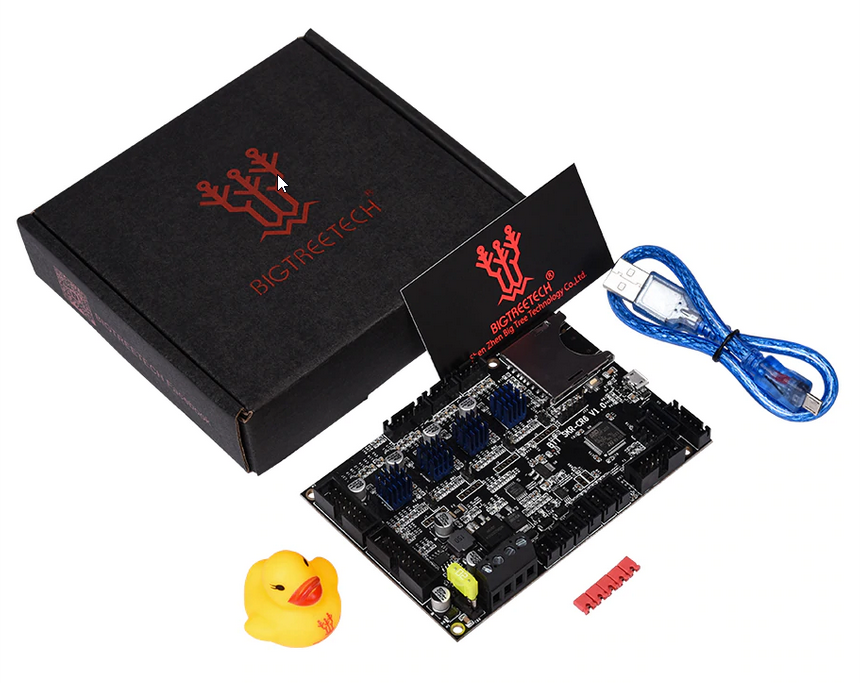
- A BTT SKR CR-6 board. You can get it on on AliExpress, and also at 3DJake or Amazon.
- Screwdrivers.
- You must have set-up your development environment so you can compile Marlin firmware.
I recommend additionally:
- A BTT TFT43 or TFT50.
- I used a spare stock touch screen from my Creality CR-6 SE (so I could run the Community Firmware) - and you may be able to reflash the stock touch screen - this is quite experimental.
- The BTT TFT a standard solution offering both a touch screen mode and classic Marlin UI.
- The BTT TFT43 or TFT50 are the only options that are likely to fit well in the position of the original touch screen. The TFT35 with rotary knob is too high, and the TFT70 is huge. The TFT28 is not compatible (needs EXP1 and EXP2 cables).
- Wire strippers and ferrules. While you have the printer open, you might as well remove the tinned ends of the wires as demonstrated in the TH3D CR-6 live stream. Optionally you can put ferrules on it.
Removing the current board
First we need to take the current board out.
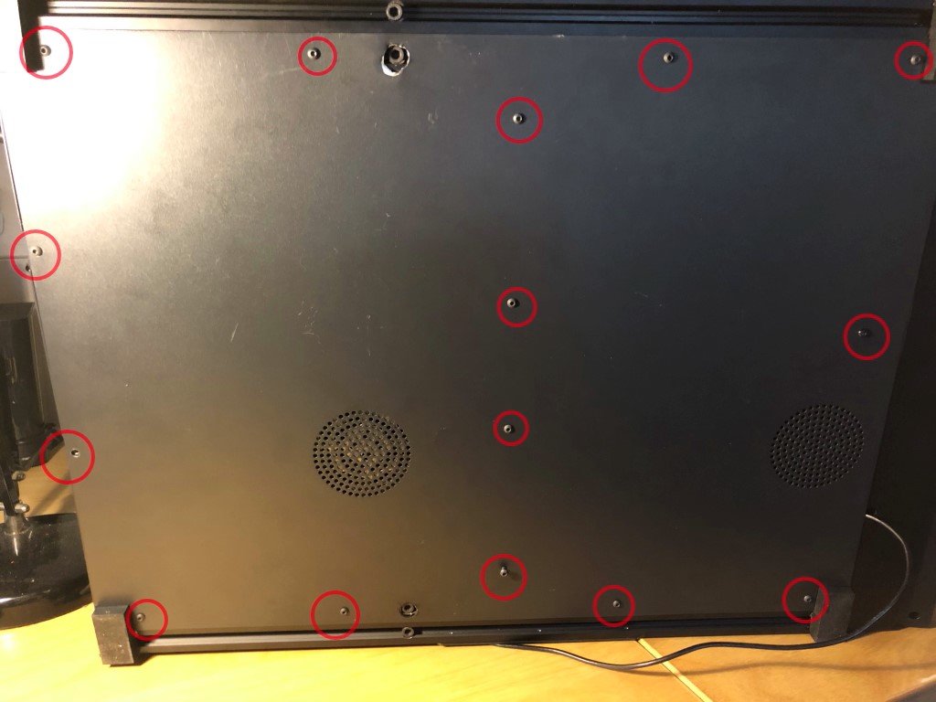 You need to remove 15 M3 hex screws. Note that not all screws have the same length.
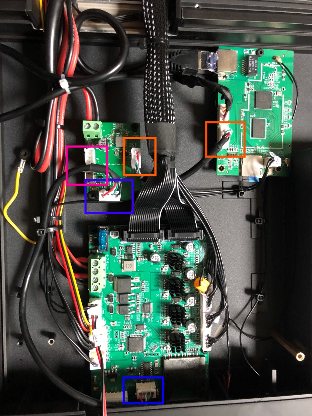 As shown in my CR-10 Smart USB article - these are the most important internals. In orange the connection to the Creality wifi box, in blue the connection from the junction board to the internal USB header of the motherboard and in in pink a header and micro-USB connector for the default configuration.
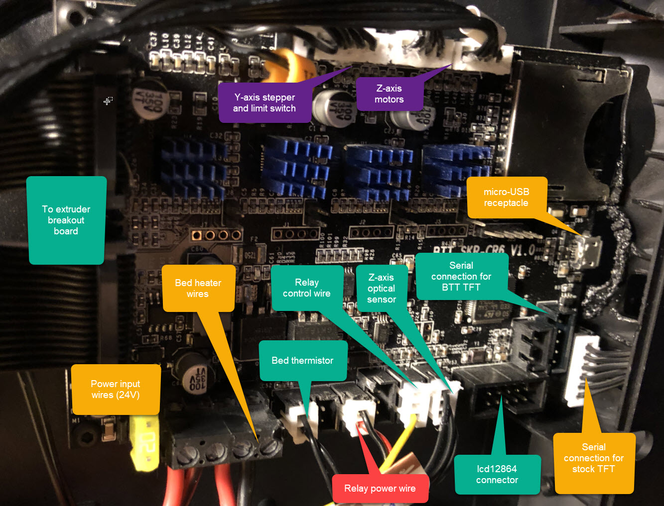
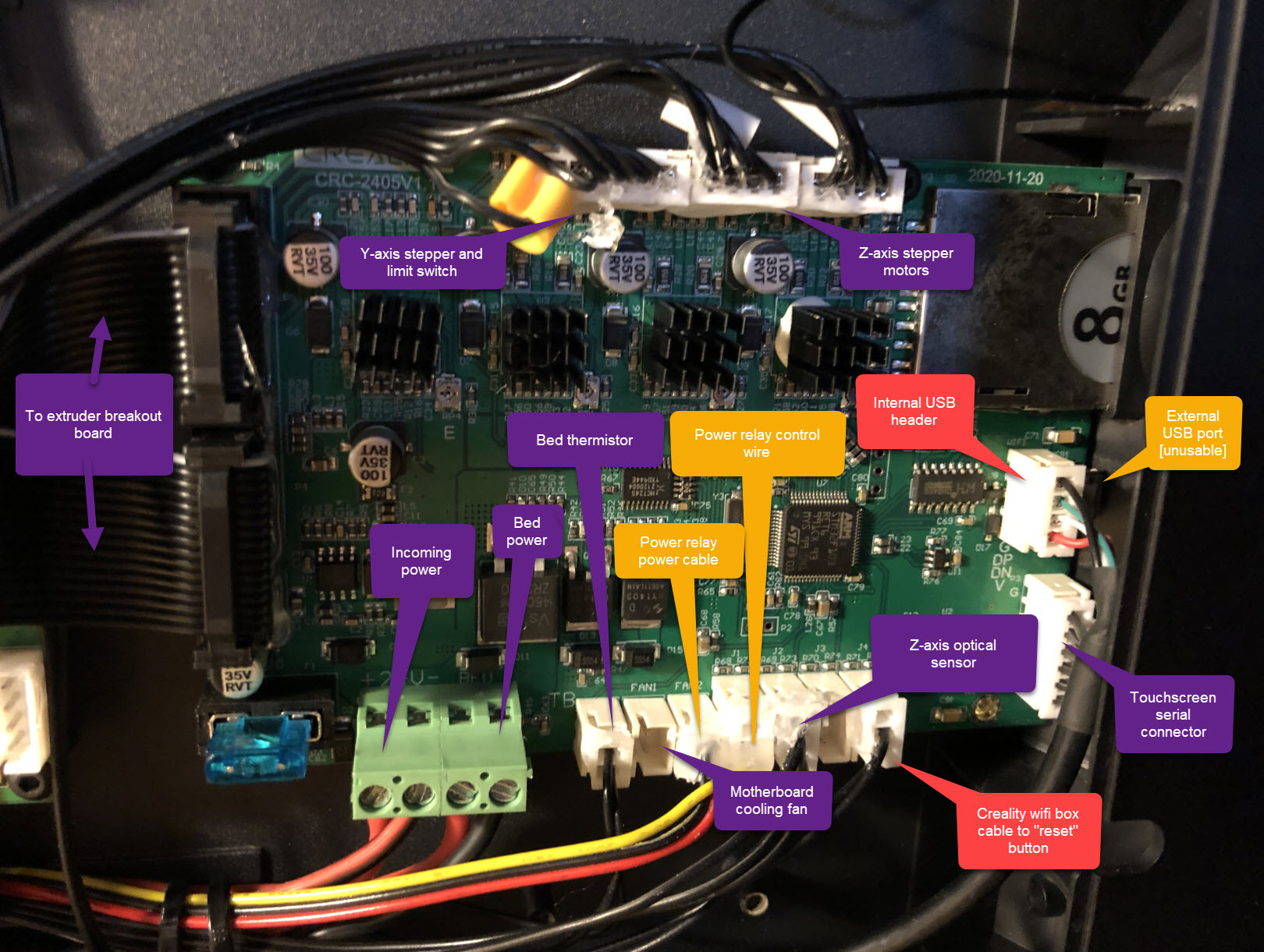 Wiring overview of the stock motherboard. Orange parts need some additional work, purple can be changed as-is and does not have an alternative
As with any Creality printer, a lot of these connections are glued in with hot glue. You can use a few drops of IPA and tweezers to get the glue loose. Label the cables so you don’t loose track of it.
Take note of the USB-connector. You need to make a hole in the front if you want to use the USB connector of your BTT SKR CR6 motherboard.
 The wire ends are tinned, so I untinned them. Even bare wires are better than tinned wires. Ferrules are even better.
BTT SKR CR6 and Creality CRC-2405V1.1 side-by-side
Pictures below show the two boards side by side.
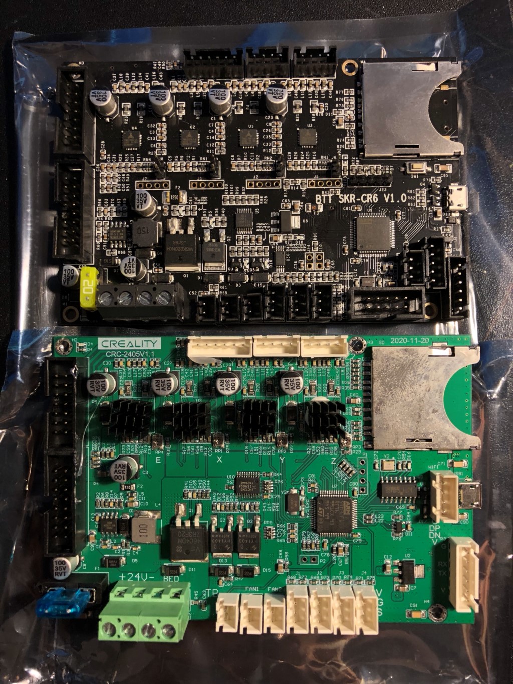 The internal USB header is not present on the BTT SKR CR6 board. Maybe in a future revision? I didn’t put the heatsinks on the board yet when I took this picture.
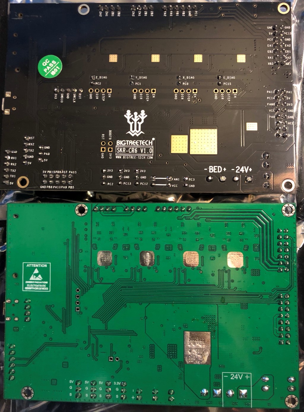 The screw holes, SD card slot and USB connector line up perfectly.
Installation
For installation, you can follow a part of my BTT SKR CR6 installation guide for the Creality CR-6. For completion, below you’Il find a wiring diagram specific to the CR-10 Smart:
 How you can wire up the BTT SKR CR6. There are some additional notes, see below.
Some additional notes on the wiring:
- Serial connection for stock TFT: As I mentioned above, CR6 Community Firmware support for the stock TFT is experimental. Therefore I recommend to connect a BTT TFT instead. You won’t regret it. For connecting a BTT TFT and/or LCD12864 check my original BTT SKR CR6 guide.
- micro-USB receptacle: The BTT SKR CR-6 board has no internal USB header. I needed to cut a pretty ugly hole in the front of the printer - or try SMD soldering. I might cover this hole up later using a flap printed in TPU.
- Power-input wires and bed heater wires: As mentioned above, it is recommended to un-tin these to prevent future electrical hazards.
- Relay power wires - see below. Note that the yellow control wire is plugged into the second port.
Relay power wires
The CR-10 Smart has a relay. That allows the firmware to turn the printer off by itself.
The relay power wires need some additional considerations. The relay of the CR-10 Smart needs 24V to stay engaged after powering on. With much experimentation I’ve found that 3.3V and 5V is not sufficient. You could use the fan port on the BTT SKR board, but with some considerations.
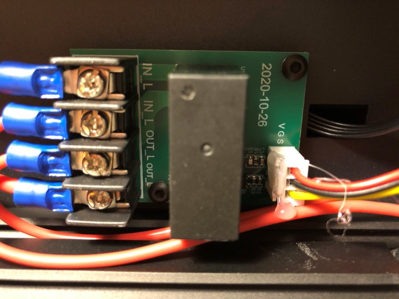 The power relay allows the printer to turn itself off. You kickstart it by pressing the button at the side. Then the firmware can turn the relay off by pulling the control wire high. A “NOT” circuit on the relay board then removes the 24V power that engages the relay.
The BTT SKR CR6 offers a firmware-controlled fan port. You can choose not to enable it in the firmware and the fan will run at full speed and the relay would work fine. However, the firmware controlled fan port allows the motherboard fan to stay off until you actually start using your printer. That makes the printer a whole lot quieter when idle! In addition, I noticed that the fan is not turned on when the bootloader is flashing the motherboard firmware. That means during firmware flashing you must hold the power button in to allow flashing to complete.
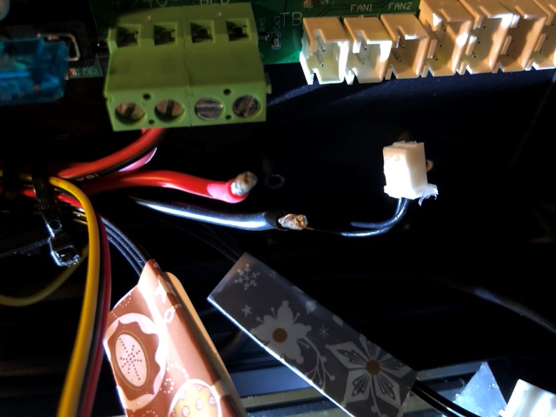
I didn’t want to compromise and leave the relay fully functional. For this reason I decided to solder the wires of the relay to the board that provides power to the Creality wifi box.
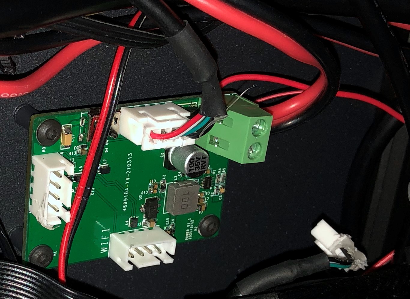 I soldered the power wires to the relay to 24V input at the bottom of the 5V power supply board. I isolated the wires so they can’t accidentally short against the frame.
Firmware changes
As a basis I took the BTT SKR CR6 configuration from the Community Firmware I have been developing.
Templates
I already have created two variations in terms of firmware changes. If you still like to do it yourself, check the “Manual changes” section below.
Take one of these configuration files:
- cr10-smart-btt-skr-cr6-with-stock-creality-tft when using the stock screen. You also need to download the TFT firmware and install it.
- cr10-smart-btt-skr-cr6-with-btt-tft when using the BTT TFT.
Place those files in the “Marlin” folder and override the existing Configuration.h and Configuration_adv.h. Then compile and flash the firmware.
Manual changes
Depending on if you have a BTT TFT or wish to use the original TFT (you’Il need to flash the Community Firmware on it and rotate it 90 degrees!), you need to take either of these configurations as an template:
- [btt-skr-cr6-with-stock-creality-tft(https://github.com/CR6Community/Marlin/tree/extui/config/btt-skr-cr6-with-stock-creality-tft) when using the stock screen. You also need to download the TFT firmware and install it.
- btt-skr-cr6-with-btt-tft when using the BTT TFT.
Also make sure you have set-up your development environment.Then, edit the sections as stated below:
PSU control
Change this:
//#define PSU_CONTROL
//#define PSU_NAME "Power Supply"
#if ENABLED(PSU_CONTROL)
  #define PSU_ACTIVE_STATE LOW      // Set 'LOW' for ATX, 'HIGH' for X-Box

  //#define PSU_DEFAULT_OFF         // Keep power off until enabled directly with M80
  //#define PSU_POWERUP_DELAY 250   // (ms) Delay for the PSU to warm up to full power

  //#define PSU_POWERUP_GCODE  "M355 S1"  // G-code to run after power-on (e.g., case light on)
  //#define PSU_POWEROFF_GCODE "M355 S0"  // G-code to run before power-off (e.g., case light off)

  //#define AUTO_POWER_CONTROL      // Enable automatic control of the PS_ON pin
  #if ENABLED(AUTO_POWER_CONTROL)
    #define AUTO_POWER_FANS         // Turn on PSU if fans need power
    #define AUTO_POWER_E_FANS
    #define AUTO_POWER_CONTROLLERFAN
    #define AUTO_POWER_CHAMBER_FAN
    //#define AUTO_POWER_E_TEMP        50 // (°C) Turn on PSU if any extruder is over this temperature
    //#define AUTO_POWER_CHAMBER_TEMP  30 // (°C) Turn on PSU if the chamber is over this temperature
    #define POWER_TIMEOUT              30 // (s) Turn off power if the machine is idle for this duration
    //#define POWER_OFF_DELAY          60 // (s) Delay of poweroff after M81 command. Useful to let fans run for extra time.
  #endif
#endif
To this:
#define PSU_CONTROL
//#define PSU_NAME "Power Supply"
#if ENABLED(PSU_CONTROL)
  #define PSU_ACTIVE_STATE HIGH      // Set 'LOW' for ATX, 'HIGH' for X-Box
  #define PS_ON_PIN SUICIDE_PIN

  //#define PSU_DEFAULT_OFF         // Keep power off until enabled directly with M80
  //#define PSU_POWERUP_DELAY 250   // (ms) Delay for the PSU to warm up to full power

  //#define PSU_POWERUP_GCODE  "M355 S1"  // G-code to run after power-on (e.g., case light on)
  #define PSU_POWEROFF_GCODE "M81"  // G-code to run before power-off (e.g., case light off)

  #define AUTO_POWER_CONTROL      // Enable automatic control of the PS_ON pin
  #if ENABLED(AUTO_POWER_CONTROL)
    //#define AUTO_POWER_FANS         // Turn on PSU if fans need power
    //#define AUTO_POWER_E_FANS
    //#define AUTO_POWER_CONTROLLERFAN
    //#define AUTO_POWER_CHAMBER_FAN
    //#define AUTO_POWER_COOLER_FAN
    //#define AUTO_POWER_E_TEMP        50 // (°C) Turn on PSU if any extruder is over this temperature
    //#define AUTO_POWER_CHAMBER_TEMP  30 // (°C) Turn on PSU if the chamber is over this temperature
    //#define AUTO_POWER_COOLER_TEMP   26 // (°C) Turn on PSU if the cooler is over this temperature
    #define POWER_TIMEOUT              (45*60) // (s) Turn off power if the machine is idle for this duration
    #define POWER_OFF_DELAY            10 // (s) Delay of poweroff after M81 command. Useful to let fans run for extra time.
  #endif
#endif
The trick is that we tell Marlin that our yellow control wire controls the power supply. Are also add an automatic shutdown after 45 minutes (which is about 15 minutes after the configured hot-end idle timeout).
Probing and bed size
Next, change this:
#define Z_PROBE_FEEDRATE_FAST ((4 * 60) / 2)
to this:
#define Z_PROBE_FEEDRATE_FAST ((4 * 60) / 3)
This slows down probing a bit, but allows better accuracy.
Next, find and change:
// The size of the print bed
#define X_BED_SIZE 235
#define Y_BED_SIZE 235

// Travel limits (mm) after homing, corresponding to endstop positions.
#define X_MIN_POS -5
#define Y_MIN_POS -2
#define Z_MIN_POS 0
#define X_MAX_POS X_BED_SIZE
#define Y_MAX_POS Y_BED_SIZE
#define Z_MAX_POS 250
to this:
// The size of the print bed
#define X_BED_SIZE 300
#define Y_BED_SIZE 300

// Travel limits (mm) after homing, corresponding to endstop positions.
#define X_MIN_POS -5
#define Y_MIN_POS -2
#define Z_MIN_POS 0
#define X_MAX_POS X_BED_SIZE
#define Y_MAX_POS Y_BED_SIZE
#define Z_MAX_POS 400
This sets the bed and height limits.
This is all you need to do!
Final bits
After flashing, ensure homing and leveling the bed works as expected. If leveling or homing doesn’t work, refer to either of these guides:
- The troubleshooting section of my strain gauge article
- The first steps section in my BTT SKR CR6 installation guide
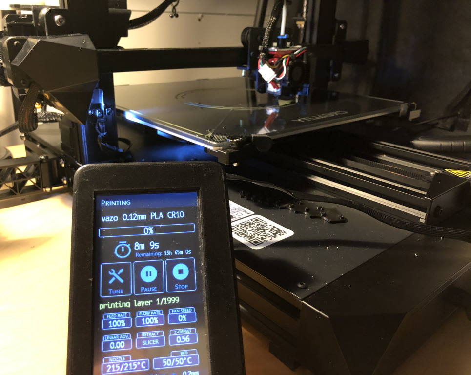
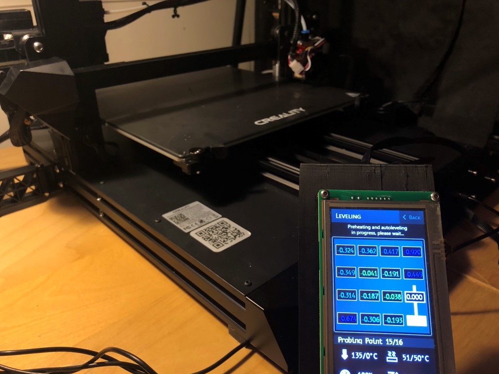 First test in progress - running leveling sequence.
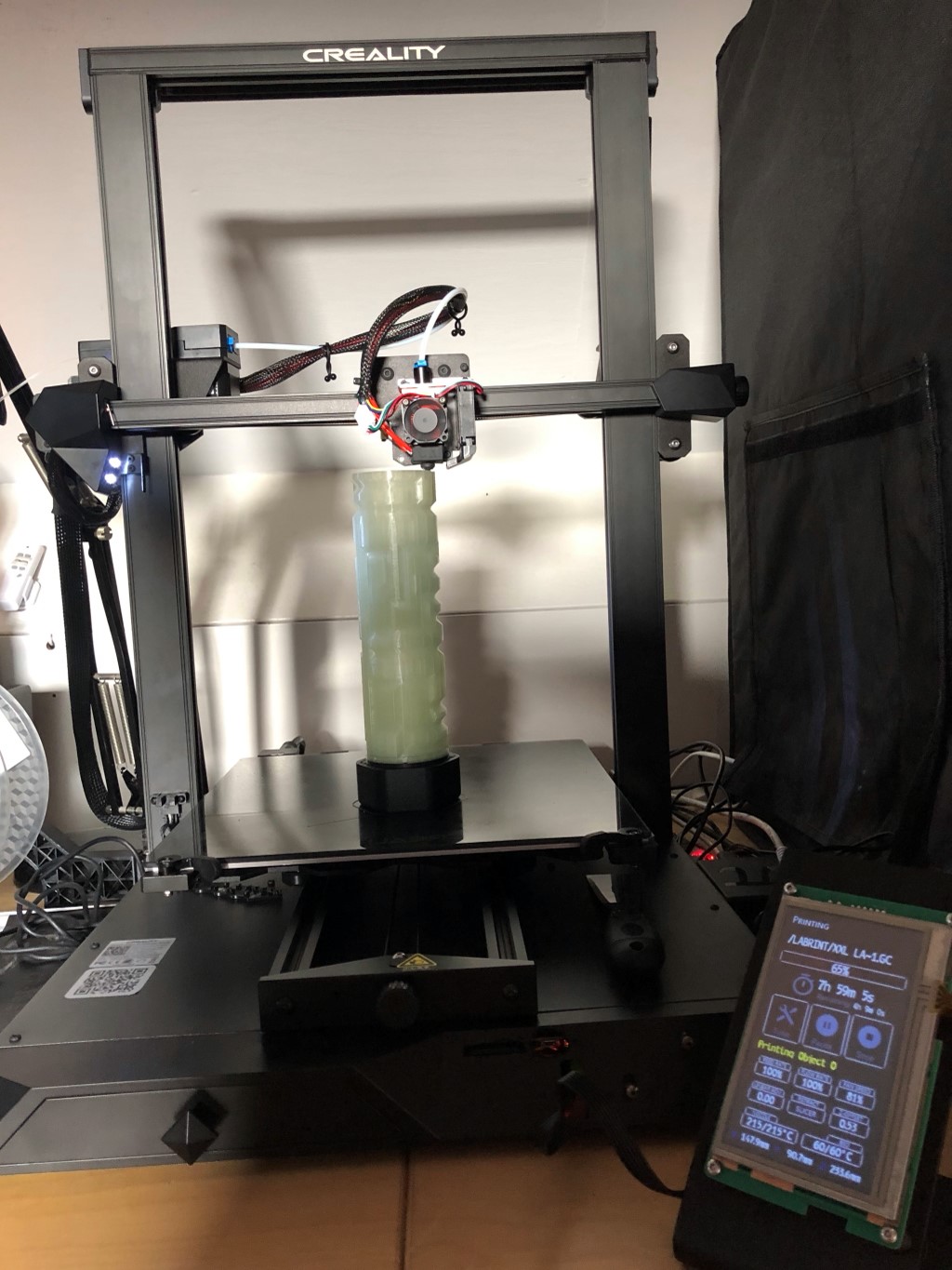 Printing the XXL Labyrinth Gift Box at 200%
Conclusion
This guide has shown you how to install a BTT SKR CR6 motherboard in the Creality CR-10 Smart. I hope it proves useful to someone. If you also like to try it, you can buy a BTT SKR CR6 board on AliExpress. Feel free to drop a comment down below or in the Community Firmware discord server.
I certainly don’t regret it - the extruder sound was quite annoying at night and now I run firmware with a few of the bugs from the stock firmware resolved.
If you’d like to learn more about the CR-10 / CR-6 bed leveling system, check out my strain gauge leveling article.
Happy 3D printing!
What are your thoughts?