On strain gauge leveling on (Creality) 3D printers: How it works and notes on accuracy
“Strain gauge leveling demystified!” or insert some other clickbait title 😉 Let’s look at how strain gauge leveling works on Creality printers, what influences the accuracy, and how to interpret the results!
Introduction
Creality introduced leveling using the nozzle of the printer with the Creality CR-6 3D printer. I’ve had two Creality CR-6 printers for over six months now and have also been developing the Community Firmware for this printer. Currently I’m testing a Creality CR-10 Smart printer which has strain gauge leveling as well.
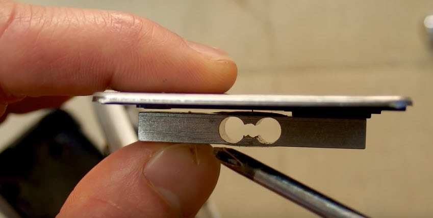
 The naked strain gauge bracket on the Creality CR-6 SE X-carriage
I’ve received a lot of questions regarding the leveling on the printer - especially regarding the new leveling screen introduced in the printer. This prompted me to write this article regarding leveling.
In this article I write about how to interpret the results, how the strain gauge leveling works and how to improve accuracy.
Interpreting bed leveling results
What I write below applies to any bed leveling probe, but to the CR-6 strain gauge in particular.
The bed leveling results say nothing about the physical state of the bed, if the probing results are not accurate. You can have all points near-zero, but if the probing isn’t accurate, you still cannot print well. If your bed isn’t perfect, the numbers are not perfect, but the probing is accurate - then won’t have trouble printing.
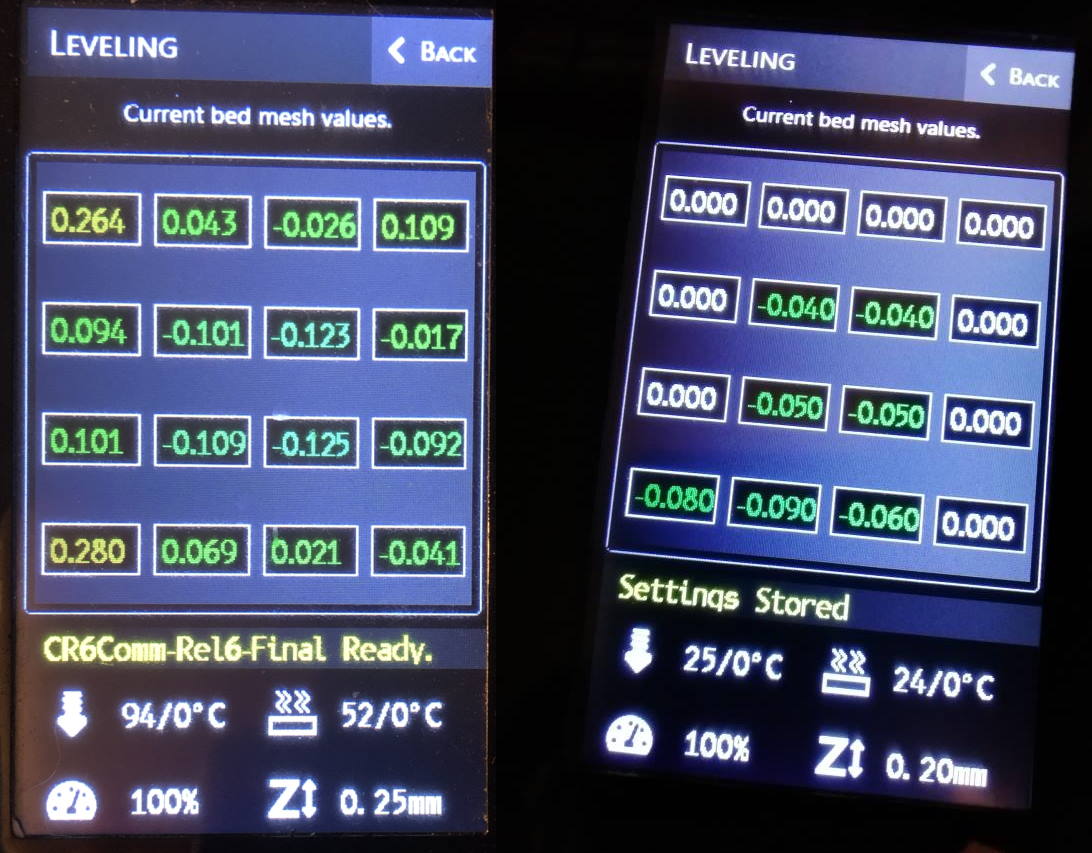 Bad mesh vs good mesh? Is any of these good or bad? The numbers can lie. Thanks to @ztakis on Github providing the picture on the right. Both meshes print right though.
Bad bed leveling is not Marlin not compensating for the mesh, but rather the mesh not being accurate. Interfere during bed leveling, then go printing and note how Marlin compensates perfectly well for the mesh. We will look into probing accuracy issues down below.
What can you do with this information then?
- You can run bed leveling multiple times and check if the numbers change much. If they do, you have a probe accuracy issue.
- You can tap a number and manually enter a new value. The values are relative to the homing position, and represents in which direction and how much the Z-axis should move to compensate for an unleveled bed.
Bottom line: If your printer prints fine, then it is no issue that the bed leveling mesh looks like a rainbow.
What is a strain gauge?
A strain gauge measures deformation on an object. The object measured is usually some kind of metal bracket or metal extrusion. On the wires of the strain gauge a voltage is applied, and when the objects experiences deformation, a millivolt signal can be read back.
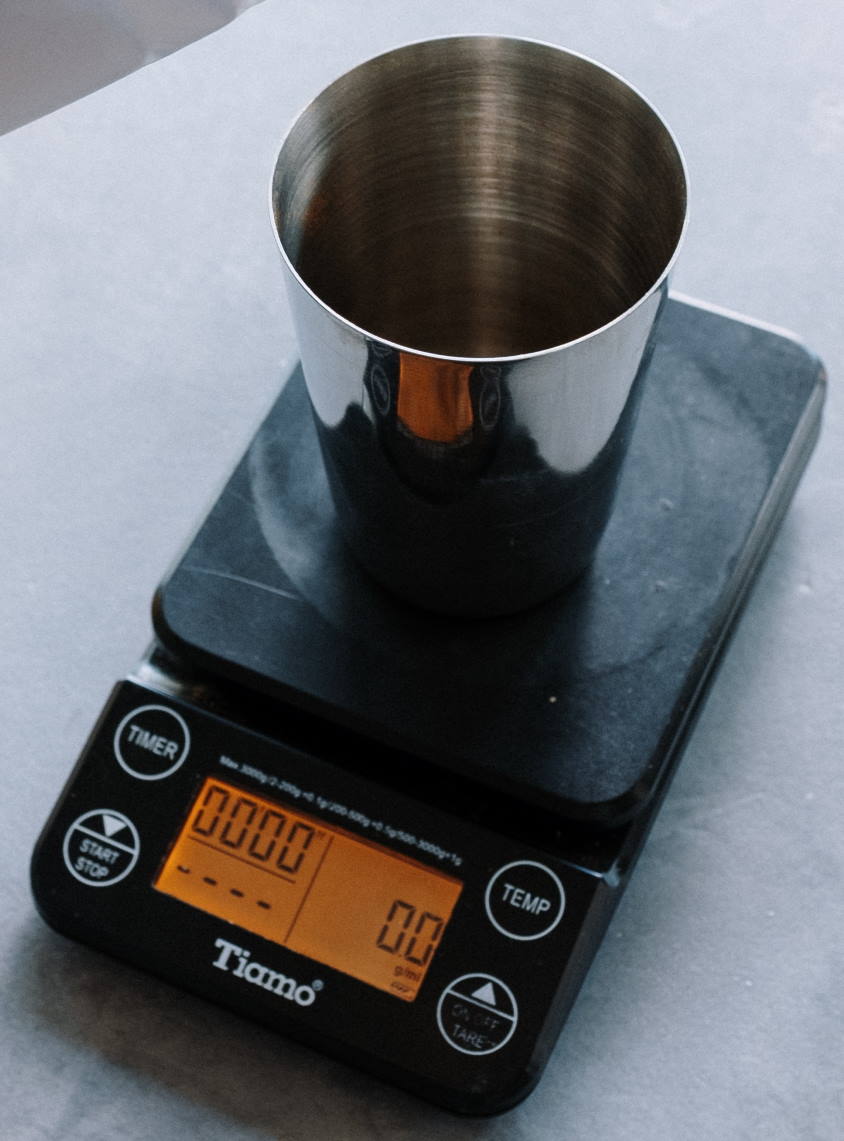 A digital kitchen scale has a strain gauge internally
 This excellent video of Diode Gone Wild explains how a digital kitchen scale works.
The CR-6 / CR-10 Smart has a similar strain gauge, which is used for leveling. That also makes that the strain gauge has a trigger weight, which is also one of the characteristics.
Characteristics of strain gauge leveling
With this knowledge, some of the characteristics of strain gauge leveling are:
- Triggers at a certain weight
- This makes it by extension more susceptible inaccuracy due to mechanical issues and slop in the system.
- It can be tared / zeroed, just like kitchen scale
- This is necessary to reduce false readings caused by the bowden tube pulling on the hotend as the X-carriage moves during the probing sequence.
- Because the nozzle effectively is the probe, there is no X/Y probe offset.
- This has the advantage that regardless how large your hot-end is, you will always be able to probe every point the nozzle can reach.
How strain gauge probing works on the CR-6
You can already guess how this works on the Creality printers with strain gauge leveling. On a very high level it works like this:
- The hot-end is mounted on the strain gauge.
- The hot-end moves down to the build plate.
- When the hot-end touches the build plate and the strain gauge bracket deforms.
- The firmware knows now that the build plate has been touched.
The optical sensor of the gantry determines when to listen to the strain gauge. It is however possible to compile the firmware so that it ignores the optical sensor (check the troubleshooting section for that).
Strain gauge leveling components
There are three major components to the CR-6 strain gauge leveling:
- The strain gauge.
- The hot-end daughter board / breakout board. This board sends a Z-endstop signal to the motherboard.
- The optical sensor on the gantry, (in my option incorrectly) called the Z-endstop.
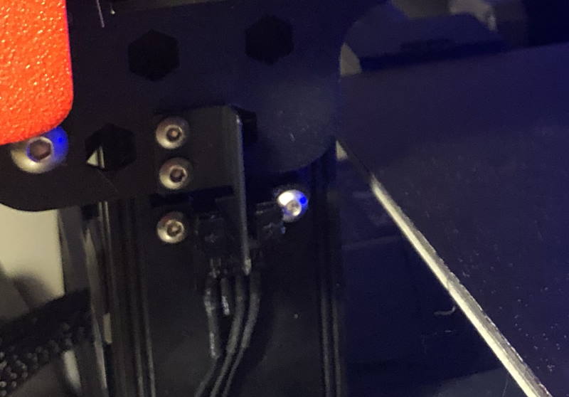 The optical sensor on the gantry.
When the optical sensor is blocked, the firmware tares the strain gauge and starts listening to the Z-endstop signal.
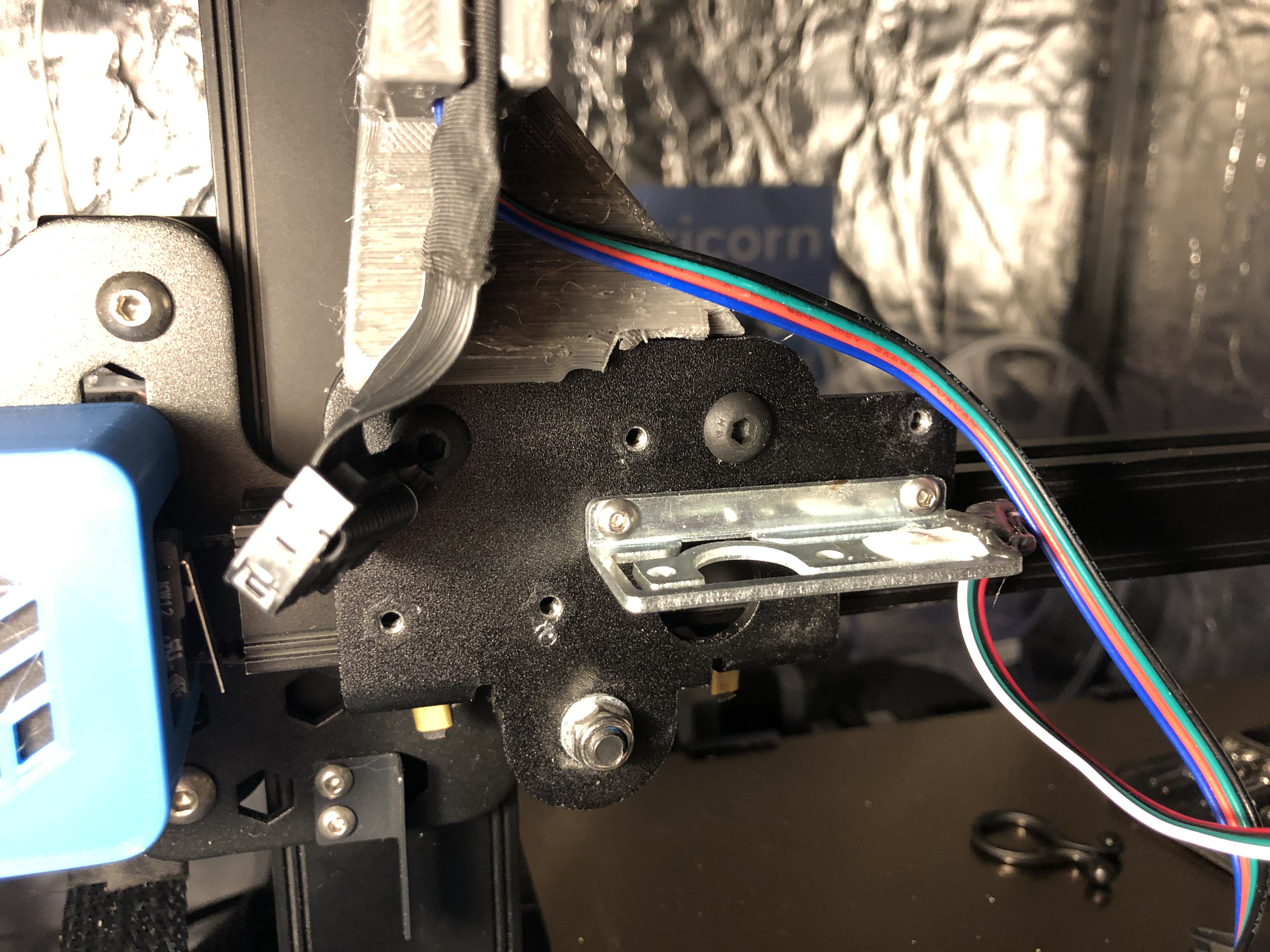
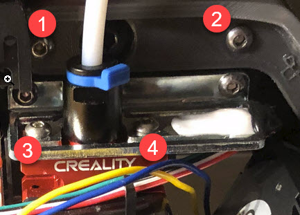
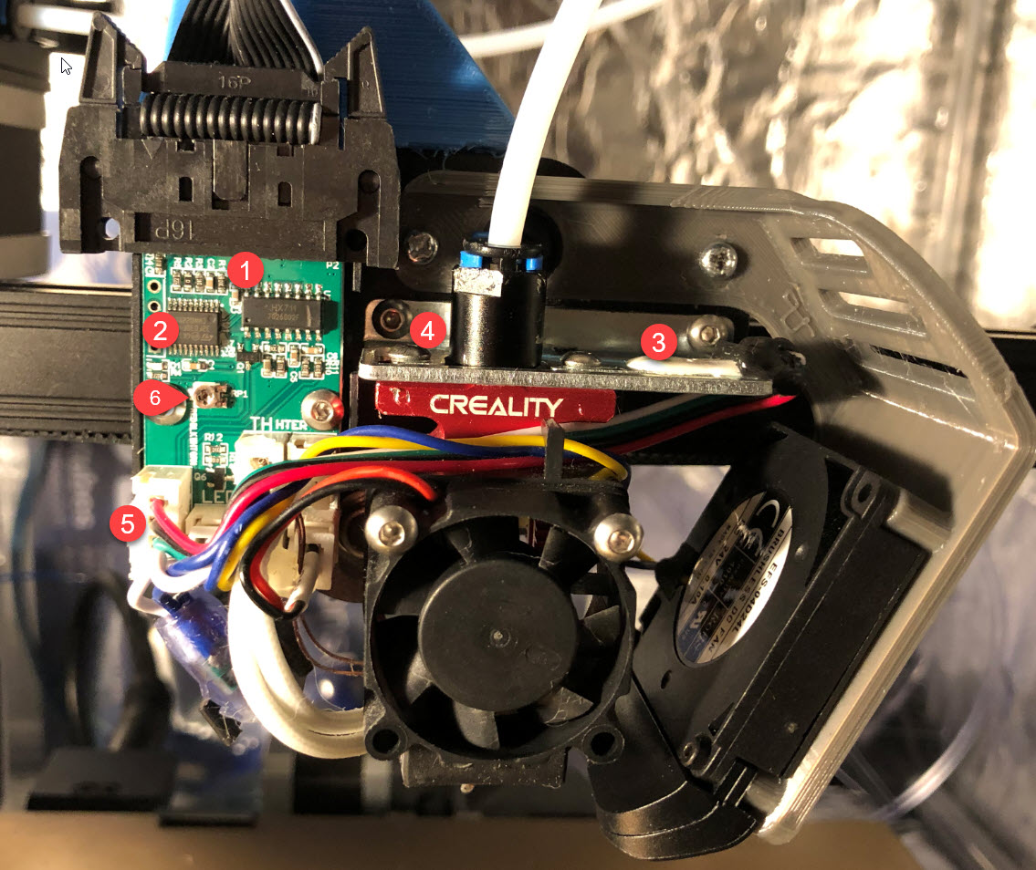 The strain gauge bracket and the hot-end daughter board.
The following components can be identified here:
- The HX711 “Analog-to-Digital converter for weigh scales” chip which reads the strain gauge itself.
- A 32-bit ARM STM32F030F4 microprocessor that runs firmware written by Creality. It reads the signal of the HX711 chip, listens to the motherboard for a tare signal, and returns a Z-endstop signal.
- The strain gauge itself, glued onto a metal bracket.
- The bowden tube fitting and mount of the hotend. Some people put a washer at the screw marked by (4) to help with leveling.
- The 4-wire connection to the strain gauge.
- A potentiometer that can be used to set a threshold for the strain gauge to trigger. It does not control a sensitivity. The potentiometer is read by the firmware on the STM32 chip (2).
If you’re interested in the firmware blob or reverse engineered schematics of this board, you can find them in the CR6Community hardware repository.
Strain gauge leveling - accuracy factors
When strain gauge leveling works, it does work perfect. When it doesn’t, it leaves a lot of things to check.
That said, I recommend to leave things as they if you don’t have bed leveling issues. There is no shame in an imperfect bed leveling mesh 😉
Trigger weight
What I’ve shown in my BIQU H2 DD mount article is that you can weight the strain gauge.
To weight your strain gauge:
- Remove the cover, so that the PCB is well visible.
- Move the X-carriage to the center position.
- Turn the printer off and then on. This is important. The strain gauge is tared when the printer is turned on.
- Place a digital kitchen scale on your printbed.
- Lower the Z-axis manually, by turning the couplers, down onto the scale.
- While lowering Z-axis, watch the scale and the hot-end daughter board. At some point after the nozzle hits the scale, and you keep lowering the Z-axis a LED will turn on. At that exact moment note the weight.
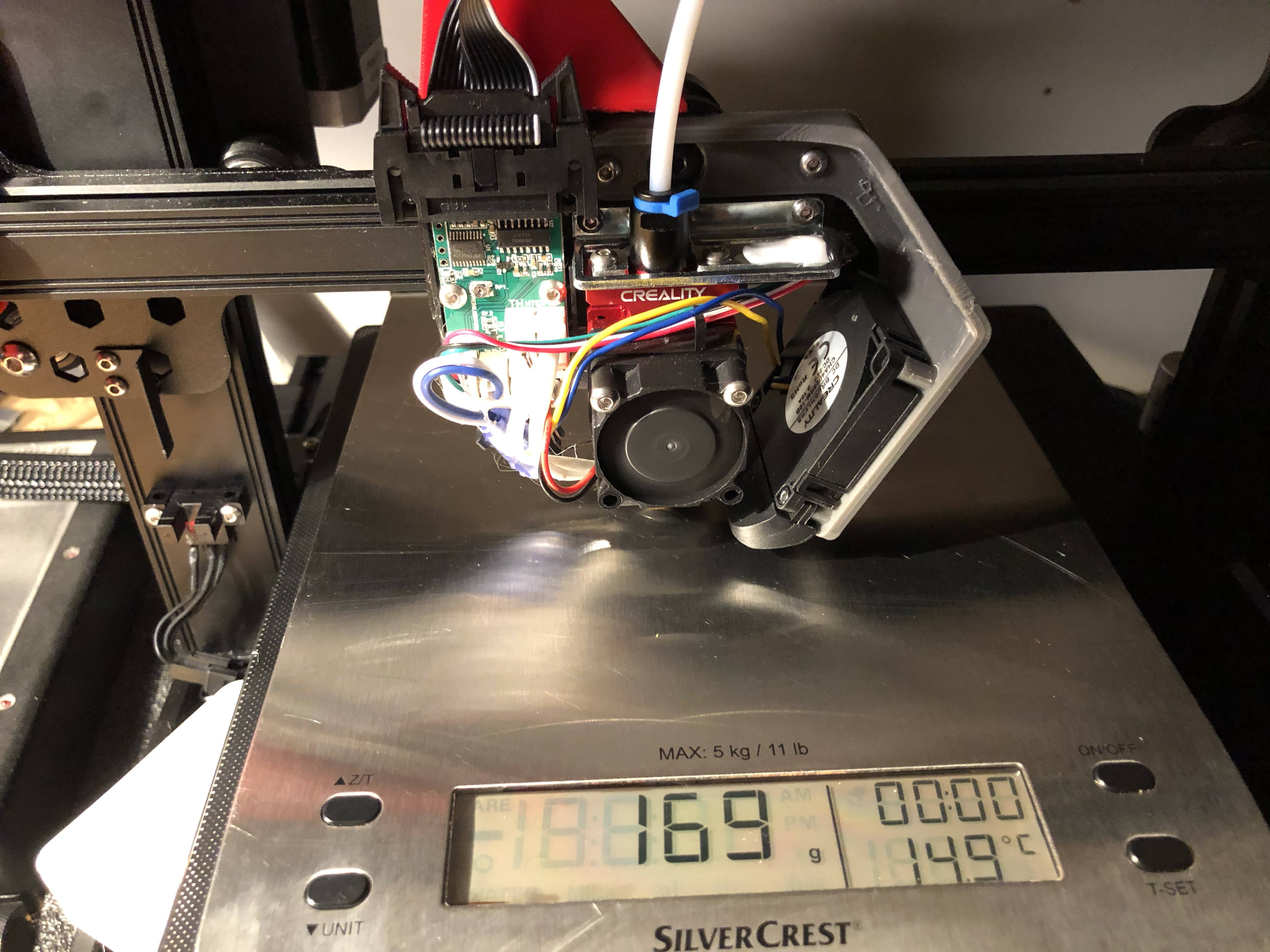 For me a weight of 160 grams worked well. Your mileage may vary.
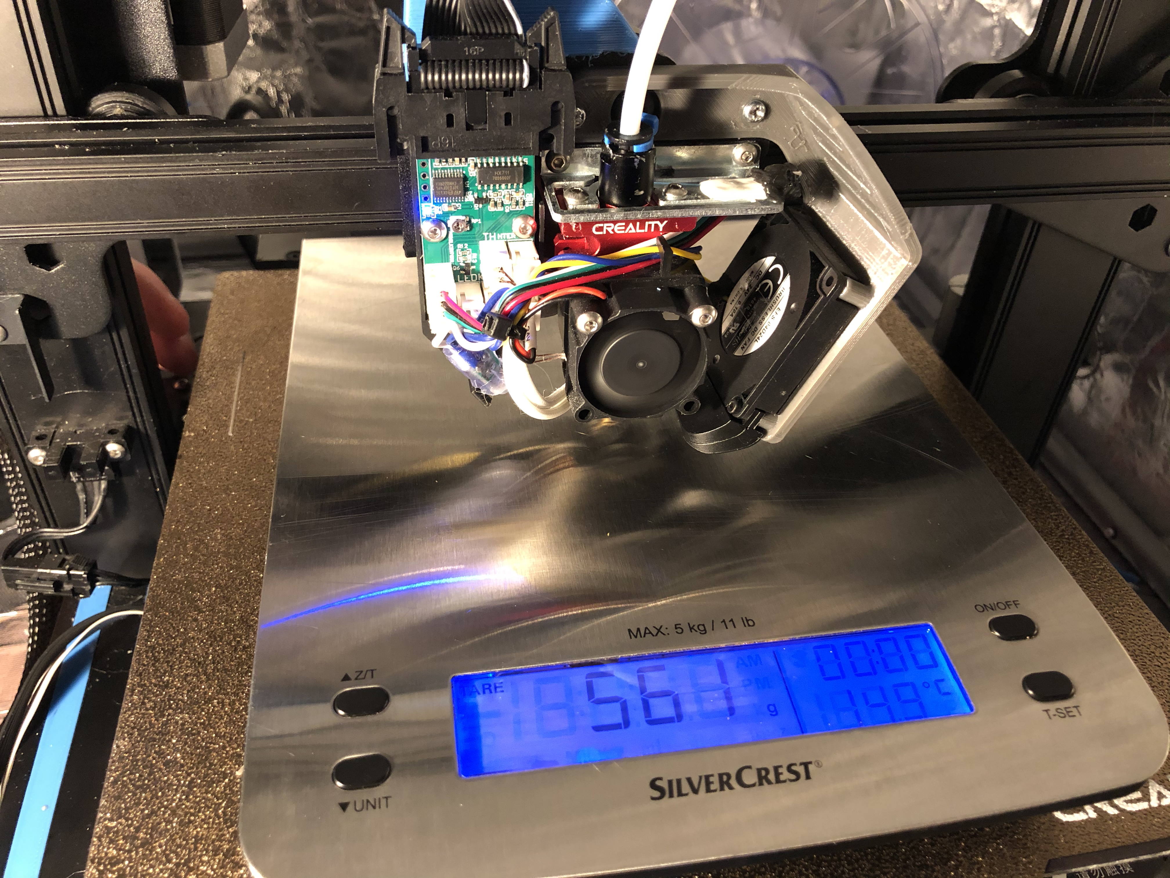 560 grams was too much for me. During bed leveling, the bed was bending in the corners.
If you want to adjust the threshold of the strain gauge you can adjust the RP1 potmeter on the board. Adjust it a tiny bit, preferably with a plastic screwdriver, then repeat steps 3 onwards. It is very important you turn the printer off and on again.
Mechanical factors
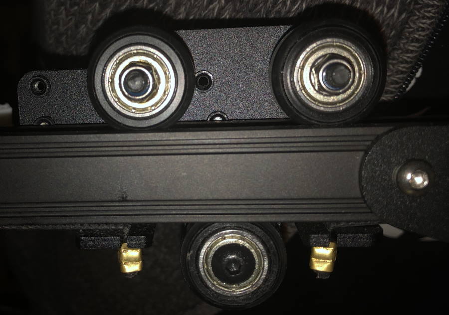 The X-carriage has eccentric nuts. If they are loose (try to move it up and down!) it will affect bed leveling, even when it might not always affect printing.
 I had the screws on the strain gauge (1 and 2) coming loose once, during a long vase print. It caused a pretty bad layer shift. In addition you may want to consider adding a washer on (3).
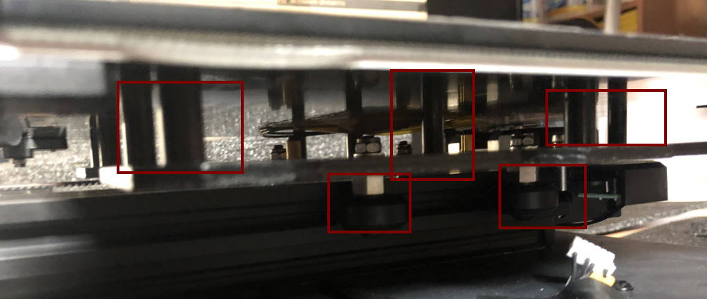 Spacers and eccentric nuts
Under the hotbed there are the eccentric nuts. These need to be tightened.
Spacers under the hotbed
There are also the spacers on which the hotbed rests. Some people have reported that their spacers don’t have the same height. That can cause “bending” of the bed during probing.
You can either use aluminum foil or sand paper to make sure they are of the same height. The point is that the bed must be supported well. Some people have replaced the spacers with silicone spacers and reported success. Others have tightened or loosened (some of) the screws of the hotbed.
X-axis not level
When the X-axis is not leveled, the bed leveling might be inaccurate.
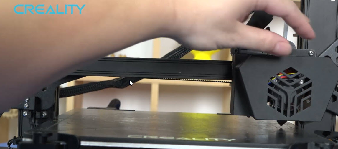 This video of Creality explains how to level the X-axis.
I use a slightly different procedure for leveling the X-axis:
- Lower the X-axis to the bed.
- I loosen the grub screws of the timing belt on the left side.
- I loosen the grub screws holding the lead screw to the coupler of the right side stepper motor.
- Then I level the X-axis as shown in the video, but by turning the timing belt.
- I verify everything is good and tighten the grub screws again.
Firmware
It is a bit like Toilet duck advising Toilet duck, but I do recommend the Community Firmware for the CR6.
We’ve found out during the development of the beta 5 release that electrical noise can greatly interfere with the accuracy of the probe. Electrical noise like the PID signal to the hotend heater cartridge, while the HX711 chip reads a tiny millivolt signal from the strain gauge itself.
For this reason the firmware turns the heaters off while actual probing happens. Turn turning “better accuracy” off from the leveling settings and re-level the bed. Note how much the leveling points change.
Troubleshooting
Some common issues and troubleshooting steps below. Note that “your mileage may vary”.
My bed leveling is inaccurate
Check the previous chapter “Strain gauge leveling - accuracy factors”.
If all else fails
If you still can’t get proper bed leveling results, you may want to try manual bed leveling. It might also be worth to buy a new strain gauge. I’ve had one bad strain gauge myself, and replacing it fixed the problem (on my CR-10 Smart).
 You can always resort to manually correcting the leveling mesh
When viewing the bed mesh, tap a number and manually enter a new value. The values are relative to the homing position, and represents in which direction and how much the Z-axis should move to compensate for an unleveled bed. You can also do this from Octoprint via gcode G29 W I[number] J[number] Z[z-height].
During homing the nozzle is pushed into the bed and doesn’t stop
It is possible either your hot-end breakout board or the optical sensor (or its cable) has failed.
If you happen to run the Community Firmware, then you can issue gcode M119 from Octoprint or computer with Pronterface. You will receive a response:
Reporting endstop status
x_min: open
y_min: open
z_min: open
probe_en: open
filament: open
Verify functionality of optical sensor: Block the optical sensor, with an Allen key for instance and issue M119, and check if probe_en says TRIGGERED. Ensure the optical sensor is plugged into the correct port (J2 for v4.5.3 boards). If you have determined your optical sensor is broken, you can compile the firmware and place \\ before #define PROBE_ACTIVATION_SWITCH. This allows the firmware to ignore the optical sensor.
Verify functionality of strain gauge mechanism: Push the nozzle up and issue M119 while you do that. Check if z_min says TRIGGERED. You can also try to decrease the trigger weight.
During leveling the bed is bending in the corners
You need to decrease the trigger weight of the strain gauge.
My nozzle always homes above the bed and during leveling it always raises in height
If you have already tried to decrease the trigger weight of the strain gauge, your strain gauge or hot-end breakout board may be broken. Check “During homing the nozzle is pushed into the bed and doesn’t stop” above. In the output of command M119 the value of z_min would always show TRIGGERED.
My nozzle (sometimes) homes above the bed or sometimes raises in height during leveling
You need to increase the trigger weight. I suspect this is a bug in the hot-end breakout board firmware. It seems to be happening if during a tare, the difference between the pre-taring and post-taring weight is not large enough.
In addition, remove any custom bowden clips or anything that interferes with the cabling or bowden tube. I recommend to print this CR-6 cable support without the bowden support.
I need to adjust my Z-offset every print
Try the Community Firmware for the CR6 and make sure “Better accuracy” is enabled in the leveling settings screen. I also recommend to use the recommended start gcode and then disable “Stabilize temperatures”.
Conclusion
The strain gauge leveling system is sometimes a difficult beast to tame. However, I hope I’ve provided some useful guidance in getting more accurate bed leveling results.
That said, maybe there is even more to it than this, so if you have any additions, please write a comment down below!
What are your thoughts?