How-to: BigTreeTech SKR CR-6 and BTT Touch screen installation on the Creality CR-6 SE
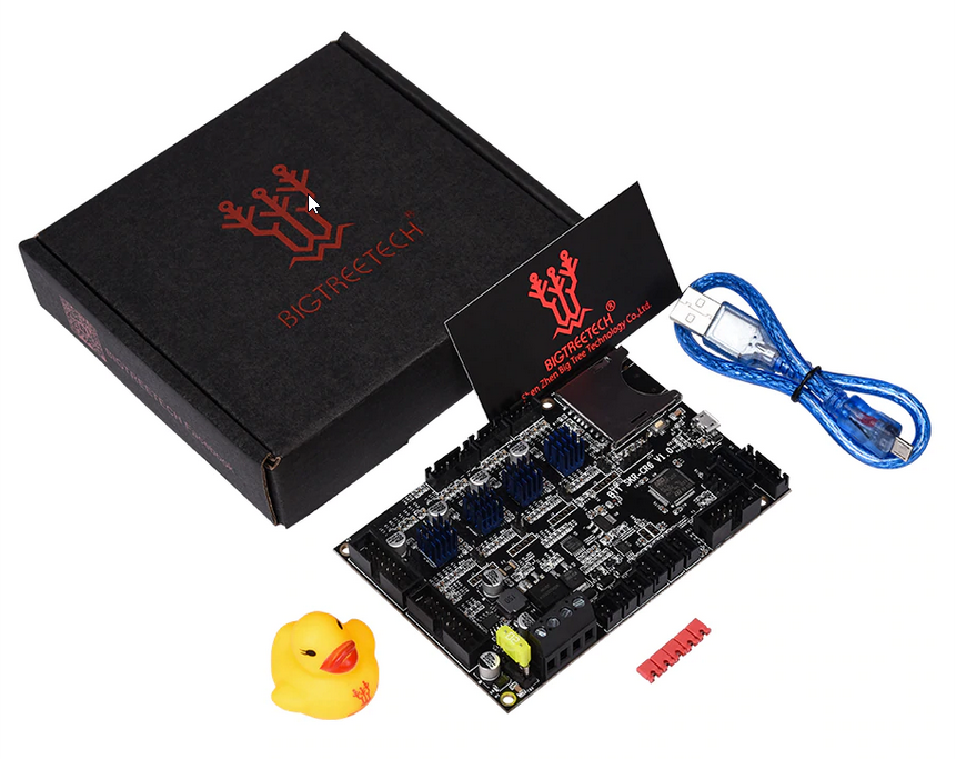
BigTreeTech sent me their motherboard replacement for the Creality CR-6 SE together with their BTT touch screen featured earlier in the BIQU B1 and available as an upgrade for many other 3D printers. The Creality CR-6 SE features a motherboard that has not been without its issues - and also my motherboard has failed within 30 days after using my unit.
Prequisites
Ensure you no have prior issues
Before you start, you want to make sure your CR-6 is running smoothly. For instance: no extrusion issues, no bed leveling issues, no weird issues with the stepper motors. If you don’t do this and you change the motherboard, it will be harder to diagnose what the cause is.
If your motherboard has an early failure and didn’t get to see the CR-6 in action, you will of course have no choice but to take a leap of faith - though you can do some hardware checks as detailed below.
If you haven’t replaced your power switch yet and you think it might get faulty at some point, replace it.
Hardware check
I strongly recommend to do a hardware check if you had a motherboard failure earlier and you have purchased a BTT board to replace your stock motherboard. The pinouts can be found further below in this article.
With your multimeter in resistance mode:
- Check the heater cartridge in the hot-end - it should measure about 16Ω
- Check the cabling to the heat-bed - it should measure about 2Ω to 3Ω
- Check the thermistor cable - it should not be shorted (less than 2Ω is likely a failed thermistor)
With your multimeter in voltage mode:
- Turn the printer on - check the wiring from the power supply. You should measure about 24V. 24.1V is okay, 25V is too high.
Prepare your tools
For this operation you need the following tools:
- The Allen keys included with the printer or similar Allen keys
- A flathead screw driver
- A camera
- FAT32 formatted SD card
- Tweezers or pliers
Optional:
- Flush cutters, like the tiny flush cutters that were included with your printer
Optional if you have a BTT touch screen:
- Extra long cables for the BTT touch screen if you want to mount it to the right side of the printer
- 3D printed mount for the BTT touch screen
Prepare the firmware
The BTT SKR board comes preloaded with firmware configured for the CR-6 SE native touch screen, yet it is a good idea to update to the latest version of the official firmware because the boards are new.
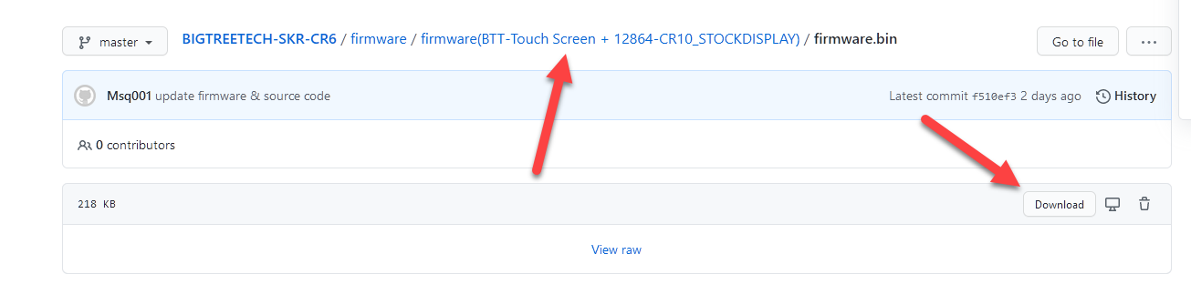
From version 5 beta onwards the community firmware is available for the BTT SKR board, but BTT provides also provides official firmware and source code of their own on their BTT-SKR-CR6 repository on Github. This firmware is based on the Creality 1.0.3.x firmware. As of now this repository is updated weekly, so if you run into issues, there is a good chance things have been fixed there.
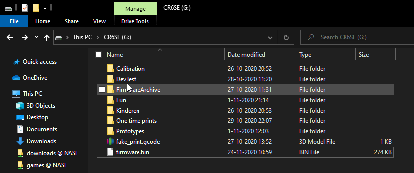 The firmware you’Il download as instructed below needs to be put as
 firmware.bin on the flash drive. Anything else will not work.
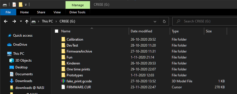 When you have eventually flashed the firmware, you’Il find that the file has been renamed to
 FIRMWARE.CUR
Make sure that you safely unmount the SD card from your computer after you’ve put the firmware on it.
Read on the instructions below on which firmware to use.
You have not purchased the BTT SKR touch screen
In this case you will want to flash the touch screen to the official Creality 1.0.3.6 firmware or to the v1.0.0-a1 community touch screen firmware. This is important if you are running the community firmware release 4 or higher or Creality firmware v2.0.0 or higher, because backward incompatible touch screen changes have been made.
The touch screen is very picky when it comes to accepting firmware updates from an SD card. You need a FAT32 formatted SD card with a 4096 cluster size. Anything else will not work.
The video below will show the general process of updating the LCD firmware.
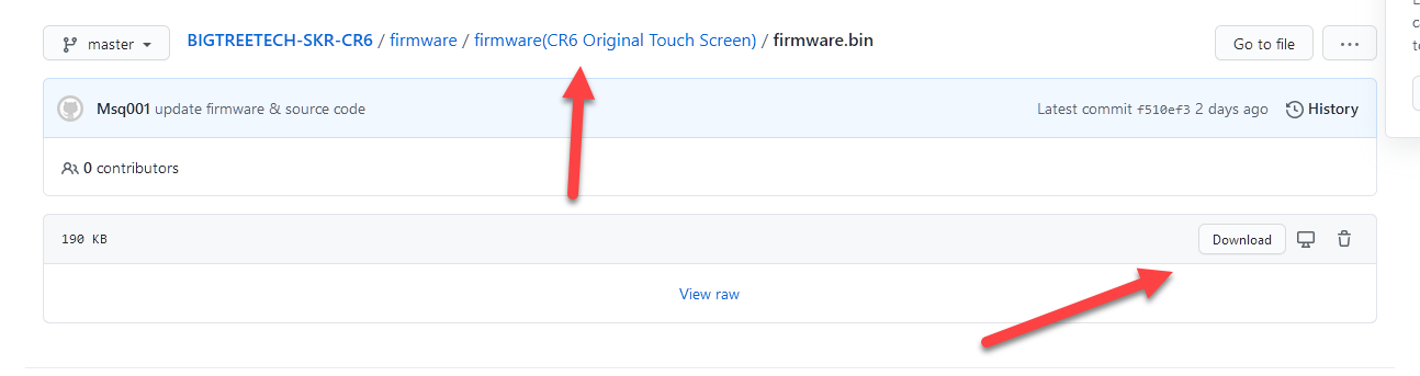
Once you have updated the firmware of the touch screen you can download the firmware.bin file from their Github page and put it on the SD card as firmware.bin in the root folder of your SD card.
You have purchased the BTT SKR touch screen
If you have purchased the BTT SKR touch screen you can leave the firmware on the CR-6 touch screen as is. You still may want to flash it to the stock firmware, just in case (check for instructions above).
Download the firmware.bin file from their Github page and put it on the SD card as firmware.bin in the root folder of your SD card.
Prepare the printer
Prepare the printer for the task. Disconnect the printer from the mains voltage, even if you have switch turned off. You don’t want to risk powering it up while you are still mounting the motherboard.
The first screw to remove is just below the bed. Remove this one before continuing. Also remove the drawer, if you haven’t already.
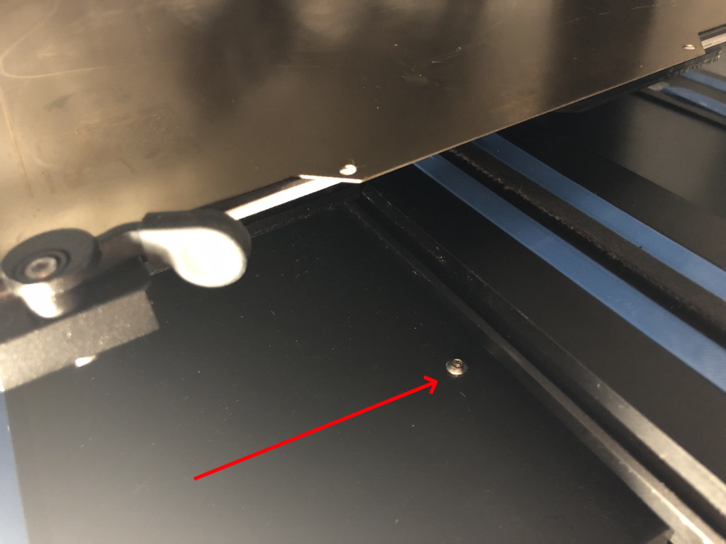 This is screw can take you by surprise if you forget it
Put the printer on its side or you can tilt it backwards if you can support it against the wall of your enclosure (if you have one).
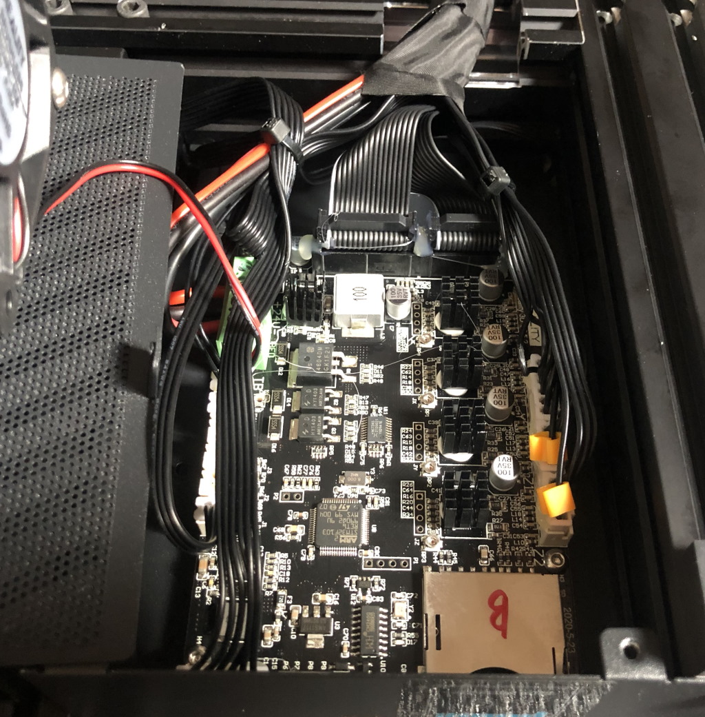
Now you can remove 3 screws holding the motherboard cover to the printer. This is also a good moment to take a picture of your current set-up. Make sure all the wiring is visible in your picture so you can reference it later on.
Unmounting the stock motherboard
Creality has glued all the connections to the motherboard. You need to carefully remove the glue from the connectors using some pliers.
 You can gently pull on the glue with pliers, it should come loose fairly easily
Then you will want to label which two wires go to the heated bed, and which two wires come from the power supply. Just mark them with a permanent marker or a bit of tape. You don’t want to mix them up when you install the SKR board. If you later lose track of which wire is which: the wire to the heated bed measures 2 to 3 Ohms on the multimeter and the wires to the power supply measure as an open circuit.
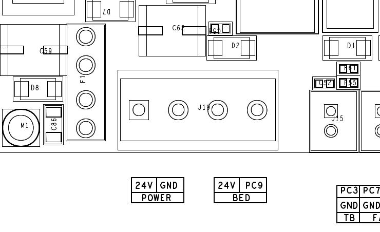
 The schematic of the Creality CR-6 SE motherboard, which I took from the user manual
Except for the thick 24V wires, all other cables have keyed connectors so you can’t reconnect them wrong. The Z-axis stepper motor connectors are interchangeable because the stepper motors are driven from a single stepper driver.
Once you got all the cables unplugged, unscrew all the small screws that hold the motherboard in place with your Allen key. Be careful! The screws are not magnetic and will get lost if you are not careful!
Safety measure: un-tinning the wires
Now you got all the wires disconnected, you may want to un-tin the wires as demonstrated in the TH3D CR-6 live stream:
This is to prevent potential issues with the screw terminals getting too hot. Take it at TH3D’s advice, and at your own risk.
Preparing the touch screen
If you have not purchased the BTT touch screen, you can skip this step Otherwise, you’Il want to do this step to make sure the cabling is routed nicely.
Remove the CR-6 DWIN touch screen cable
If you remove the drawer from the printer you can pull the “tray” the drawer slides in forward, a bit. It takes a good tug because it friction mounted to the frame. You can’t get the tray forward enough to remove it off the printer, but enough so you can remove the CR-6 DWIN touch screen cable that is routed behind it.
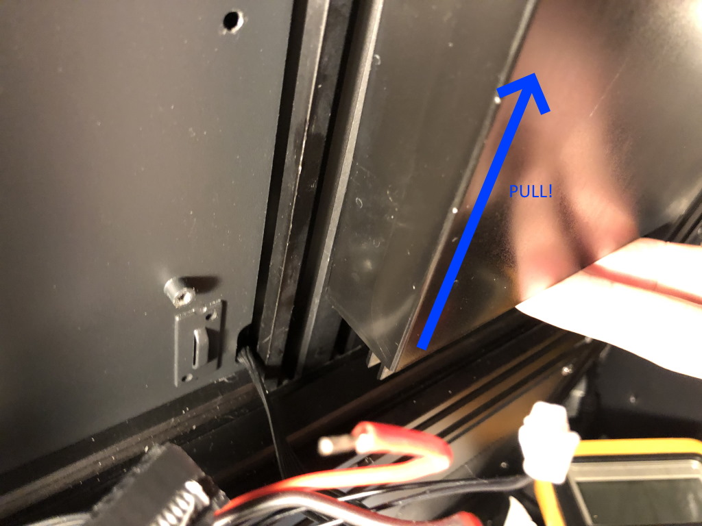 Give it a tug, it will come loose
Route new touch screen cabling
If you have extra long touch screen cables, you can route them behind the drawer. If you don’t have any extra long touch screen cables you will need to mount the touch screen on the left side.
Cabling
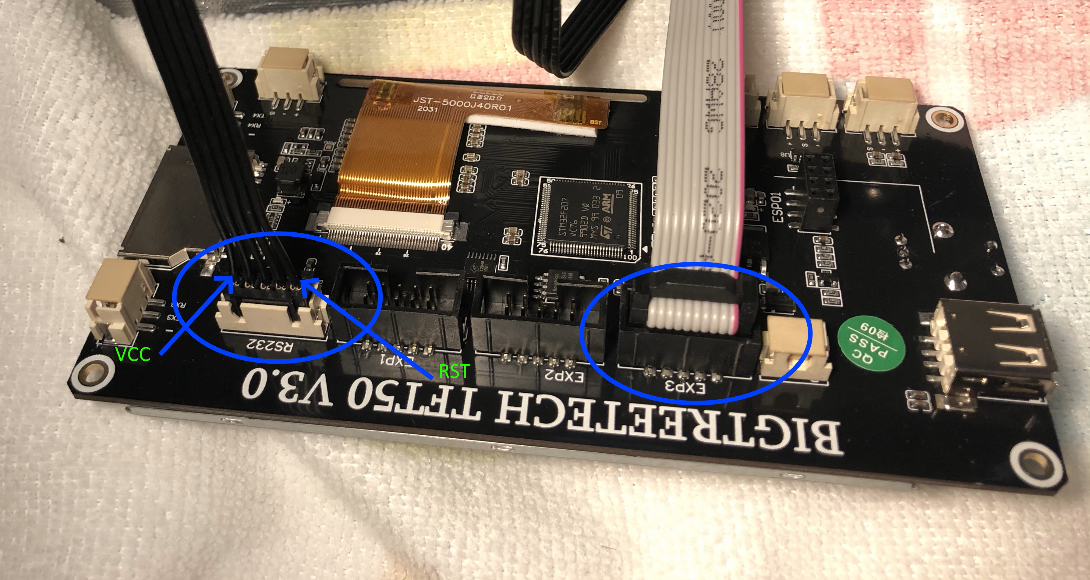
You need to wire the touch screen using two cables:
- The gray flat cable need to the plugged into EXP3 port on the touch screen
- The cable with the dupont connector goes with the JST connector into the RS232 port on the touch screen. The other side is a dupont connector, so not keyed. Take note which wire connects to the
VCCandRSTpin - you need this later when connecting to the motherboard. Refer to the documentation of your specific BTT TFT for the correct wiring
 In this case I have no mount yet, so once the touch screen is wired I will lay the touch screen on a piece of cloth to prevent it from shorting against the conductive wall of the enclosure
If your cables can’t reach the position to mount the touch screen at the right side of the printer, you will need to mount it on the left side. Temporarily you can route the cables through the motherboard cover (you need to screw the cover on loosely so you don’t pinch the cables).
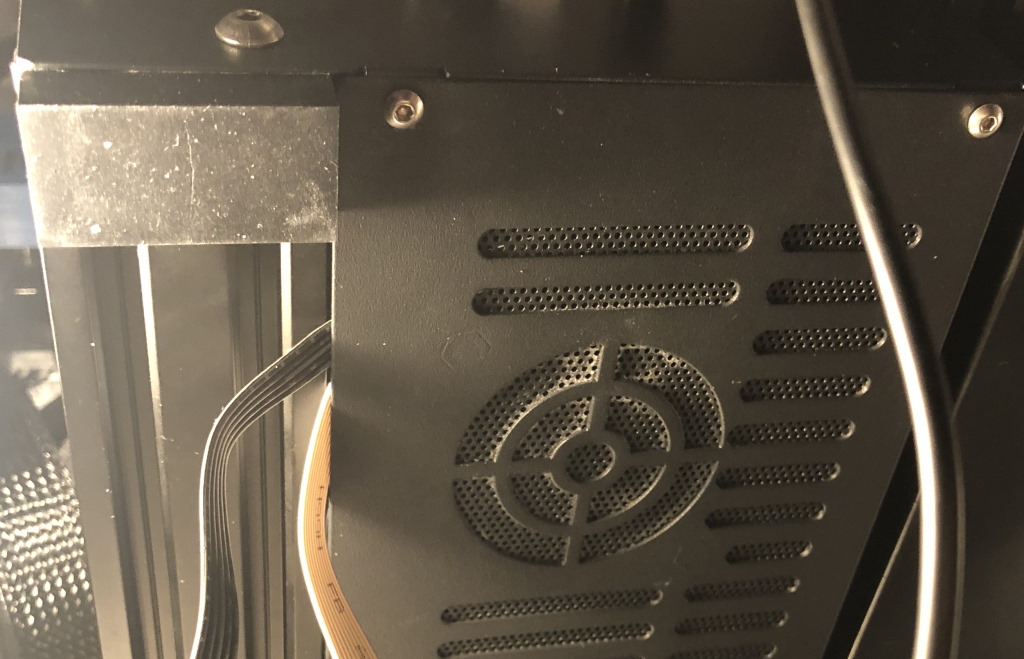 Be careful not to pinch the cabling - screw the cover on loose. I would recommend printing a new cover or some spacers for a more permanent solution.
Mounting the motherboard
The motherboard can be mounted using the small screws the original motherboard was mounted with. Do not overtighten the screws, because that will ruin the PCB.
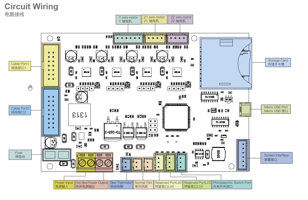
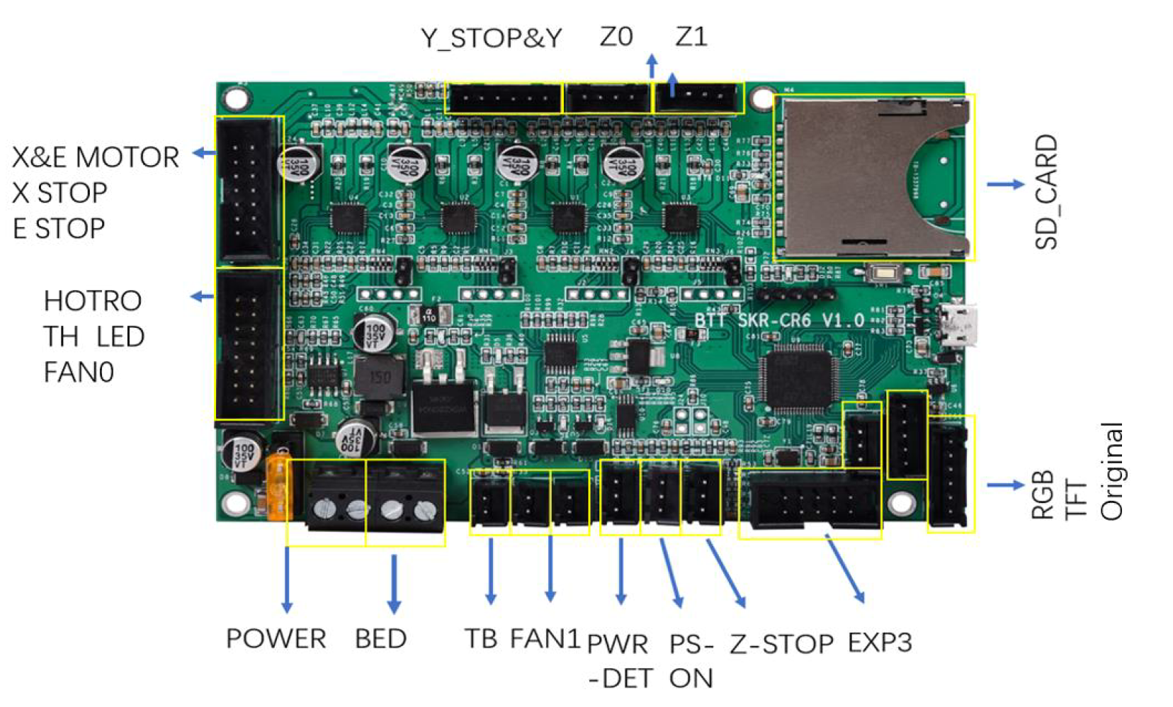 Refer to the schematic when plugging in all the wiring - always refer to the latest version of the manual
I also recommend you have the BTT board pin-out PDF handy.
 Take extra care when connecting the 24V to the screw terminals so you don’t confuse the positive (red) and negative (black) wires
Don’t mix up the wires for the bed heating and the input of the power supply. Although this board does not come with the MagicSmoke® feature, it might spontaneously develop such feature if you wire it wrong. Better check it 10 times, than regretting it one time.
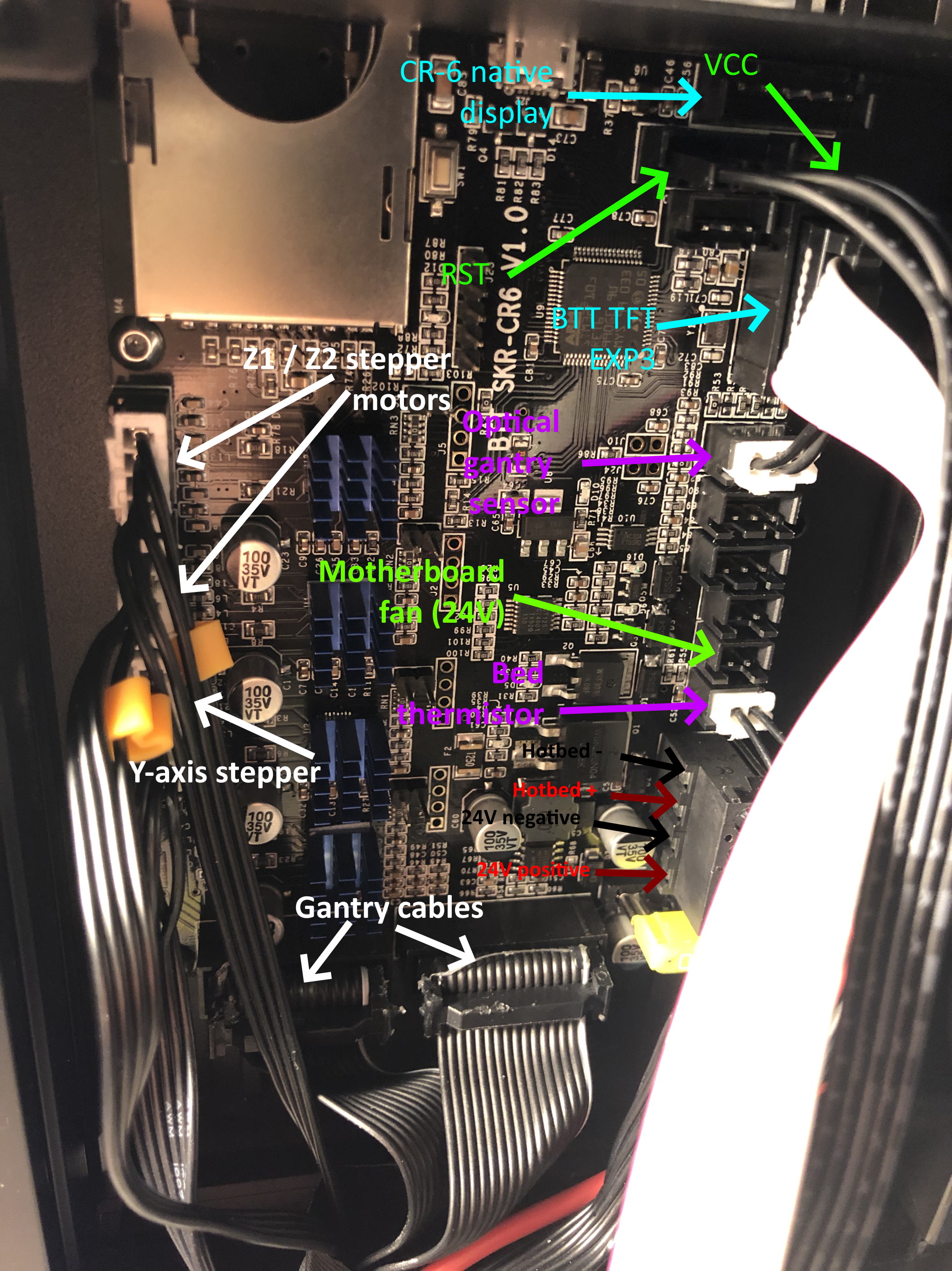 Basic overview of the wiring, take extra care with the wiring of the SKR RS232 cable because this cable is not keyed and can be connected wrong
Plug in the cabling:
- Z1 and Z2 stepper motor cables. Although the cables are interchangeable, you will find that only one cable can reach the top connector easily.
- Y axis stepper motor.
- Gantry cables. These are keyed and of a different size, you cannot do this wrong.
- Bed thermistor. A two pin cable that feels a bit fragile. Note: it goes into the bottom-most 2-pin JST port.
- Motherboard fan - once you are ready to close up the cover.
- Optical sensor to the gantry. Note: it goes into the top 3-pin JST port.
Touch screen cabling:
- If using the original CR-6 display: plug in the stock touch screen cable in the DWIN port
- If using the BTT touch screen: plug in the cable to EXP3 into the EXP3 port. Carefully plug in the dupont connector of the RS232 cable into the port. Note: the RST and VCC wire should be plugged in as noted in the picture.
BTT also delivers some jumpers, you would use these for sensorless homing. Because the CR-6 SE has endstop switches, you would not connect these jumpers.
Heat sinks
The small TMC2209 stepper driver chips need to keep their heads cool. BTT delivers small heatsinks which you can stick on the stepper driver chips. I recommend to put on the heat sinks once your motherboard is mounted and the cables are connected - you don’t have the risk of touching the heat sinks.
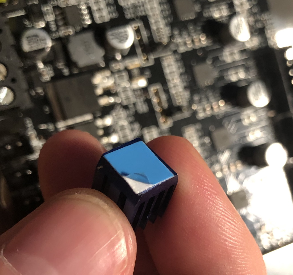 The stickers for the heat-sinks are already attached and the sticky layer is protected. Pull the protective blue cover off with tweezers.
You can just stick the heat-sinks to the drivers.
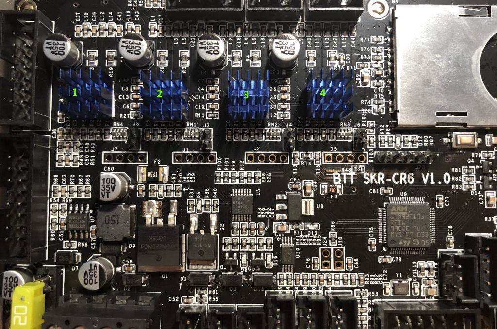 There are four heat sinks. Mount them so the small fins of the heatsinks point to the long side of the motherboard.
Prepare for powering on
Do a final wiring check before assembling the motherboard cover. Make sure the connections are well seated in the connectors, and the 24V screw terminals are properly connected.
You also want to raise the X-axis to about half of the total Z-height of the printer. Put the hot-end in the middle of X axis, and put the bed in the center of the printer. This will make sure that we have sufficient time to act if homing would fail for some reason.
If you have the Creality enclosure and use the BTT TFT, don’t put the TFT directly on the bottom of the enclosure until you have a mount. The Creality enclosure is conductive and will short out your touch screen.
Powering on!
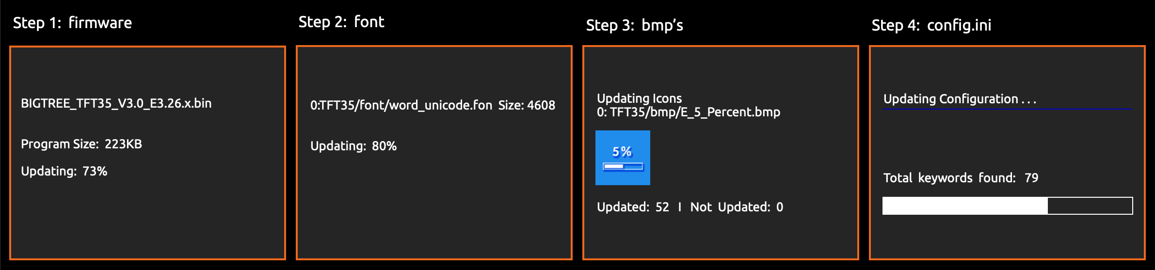
Once you’re done, put in the SD card with the firmware file and turn the printer on. The printer will take a moment to flash the firmware. On BTT boards, the firmware.bin file will be renamed to firmware.CUR after flashing has succeeded. In addition the blue LED on the hot-end will flash while the firmware is being flashed.
Firmware flashing equals hot-end LED flashing
There are some basic checks you can already perform once the printer is ready:
- Is the optical sensor at the left side of the printer connected? Note it won’t show a red light - see the known issues.
- If you push the nozzle up, does a small light mounted on the PCB inside the hot-end light up?
- Does the touch screen function? For BTT touch screens you need to test both Marlin mode and BTT touch mode.
- Can you heat the nozzle (try heating to 100 degrees)?
- Can you heat the bed (try heating to 50 degrees?
- Can you move all the stepper motors a bit?
First homing
If these checks are OK, you can continue and home the printer. Have your hand ready near the power switch to turn the printer off if necessary.
If you want you can simulate homing by blocking the optical sensor and pressing on the nozzle while the Z-axis is being homed (so when the X-axis moves down).
- If the Z-axis continues down and does not raise up, you should recheck your wiring.
- If the X-axis raises up, then down it is OK. If you don’t touch the nozzle right away, the printer will give a “homing failed” error message. Just reset the printer to continue.
Once you’ve homed the printer you are ready to go.
Next steps (for all configurations)
Leveling and custom configuration
Next you will want to:
- Level the printer
- Restore/calibrate e-step settings if you’ve changed them on your previous install
- Restore other configuration you may have modified.
You also may want to do a PID autotune if you find that the printer is having difficulty to maintain temperature.
Next steps (when using the BTT Touch Screen)
Touch screen firmware upgrade
If you have the BTT touch screen, you can upgrade the touch screen firmware. Often new versions of the touch screen firmware are released on the BTT TouchScreenFirmware Github repository with new features and bugfixes.
Gcode previews
If you have the BTT touch screen, you may want to download and install the BigTreeTech Cura plugin so that 3d model previews become available for your sliced gcode.
 The Cura plugin will allow the SKR touch screen to display thumbnails if you print from the SKR touch screen. I’m not aware of a similar plugin for PrusaSlicer.
Print a touch screen mount
There are several mounts already available:
- I designed this TFT50 mount that mounts to the left side of the printer
- A TFT35 mount that mounts to the right side of the printer
There is also a CR-6 collection available on Thingiverse.
Until you have printed something: be careful.
Known issues
There are some known issues with this BTT board:
-
The 5V USB tape workaround is still necessary. Although I don’t think this BTT SKR board will blow up your computer or Raspberry PI like the Creality board might have done, the board does take power from the 5V USB pin. This causes an endless power cycle because everything in the printer powers on, then off, then on again.
-
The optical sensor on the gantry is undervolted and for this reason the little red LED does not turn on. The sensor does appear to be functional, but because it receives 3.3V from the SKR board instead of 5V from the SKR board it doesn’t have enough power to show the LED. Don’t worry, the optical sensor is still functional - but it won’t give an indication that it does.
-
When using the BTT TFT, for leveling, it will not pre-heat the hot-end and bed. Consider pre-heating it yourself or using the community firmware when it becomes available.
-
According to the BTT manual, the USB-stick input of the BTT TFT is not functional yet. This is expected in a future update. I haven’t tested yet whether that is actually true or that Marlin can’t access it and you must print from touch mode only.
-
For full disclosure: Two components (D1 and Q2) on my SKR motherboard were faulty, causing a short when heating the hot end. At the moment I’m convinced this was just bad luck and I was able to (temporarily?) fix this myself by replacing them and some solder work. I don’t know if I got lucky or it is a testament to the design of this board that this hasn’t caused a severe cascade failure that ruins the entire board.
Conclusion
I hope this guide has helped you install the Big Tree Tech SKR motherboard on your CR-6. If you have any suggestions or remarks, please let me know.
From december 2020 onwards the community firmware for the BTT SKR board is available on Github
If you like to give me a cup of coffee for all these sleepless nights, please check this link. I appreciate it! 😄
What are your thoughts?