How-to: The Creality CR-6 BIQU H2 Direct Drive extruder mounting kit
About a week ago I received the BIQU H2 (hydrogen) direct drive extruder. This direct drive extruder is one of the pinnacles of the new BIQU BX 3D printer. BIQU has released their direct drive extruder separately so it can be mounted on other printers. I have a Creality CR-6 and due to the bed leveling system this will take a few extra steps. This article will explain how to mount it to the Creality CR-6 SE or MAX 3D printer.
Introduction
This mod will allow you to mount the BIQU H2 direct drive extruder to your Creality CR-6 SE or MAX.
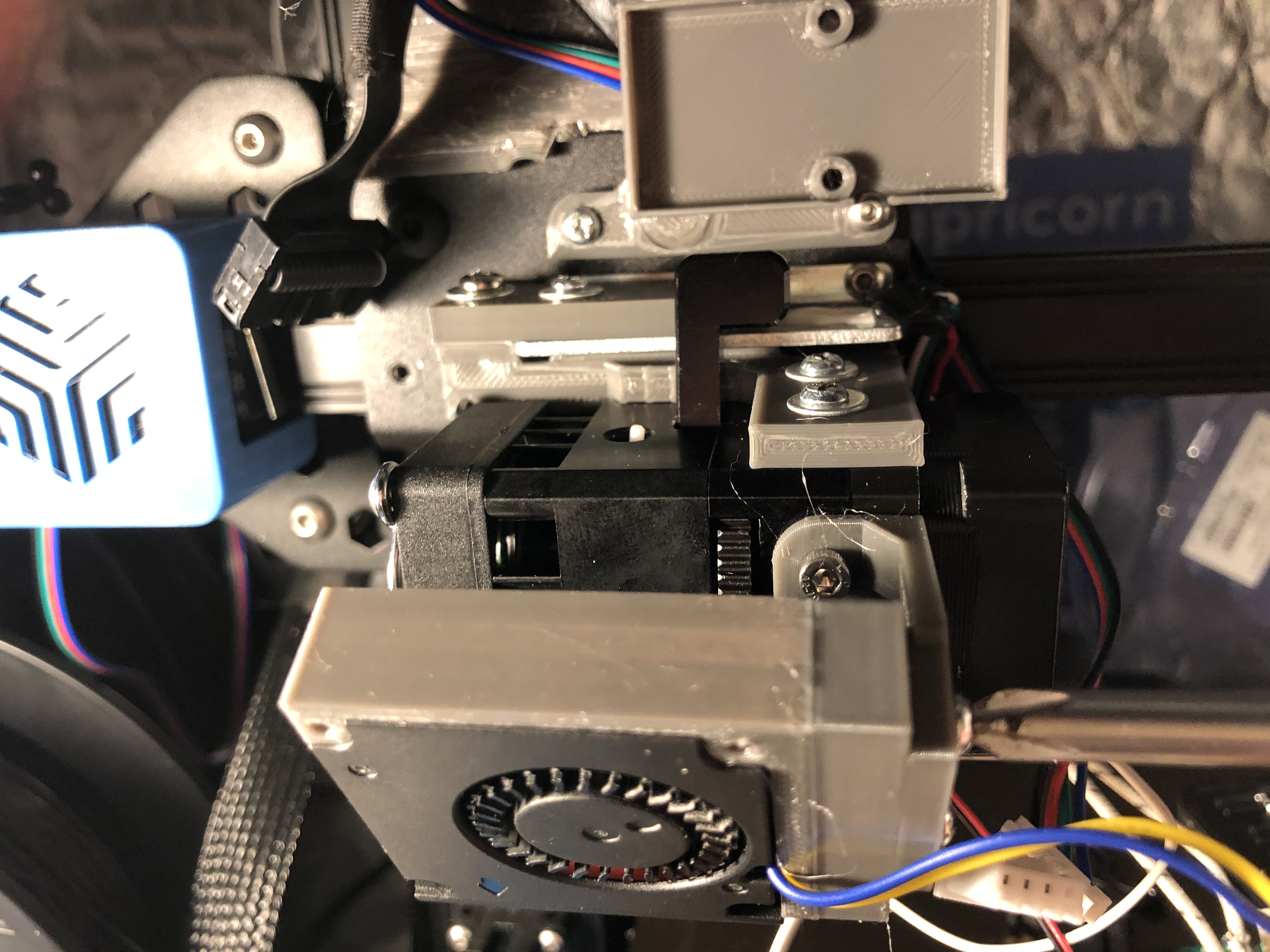
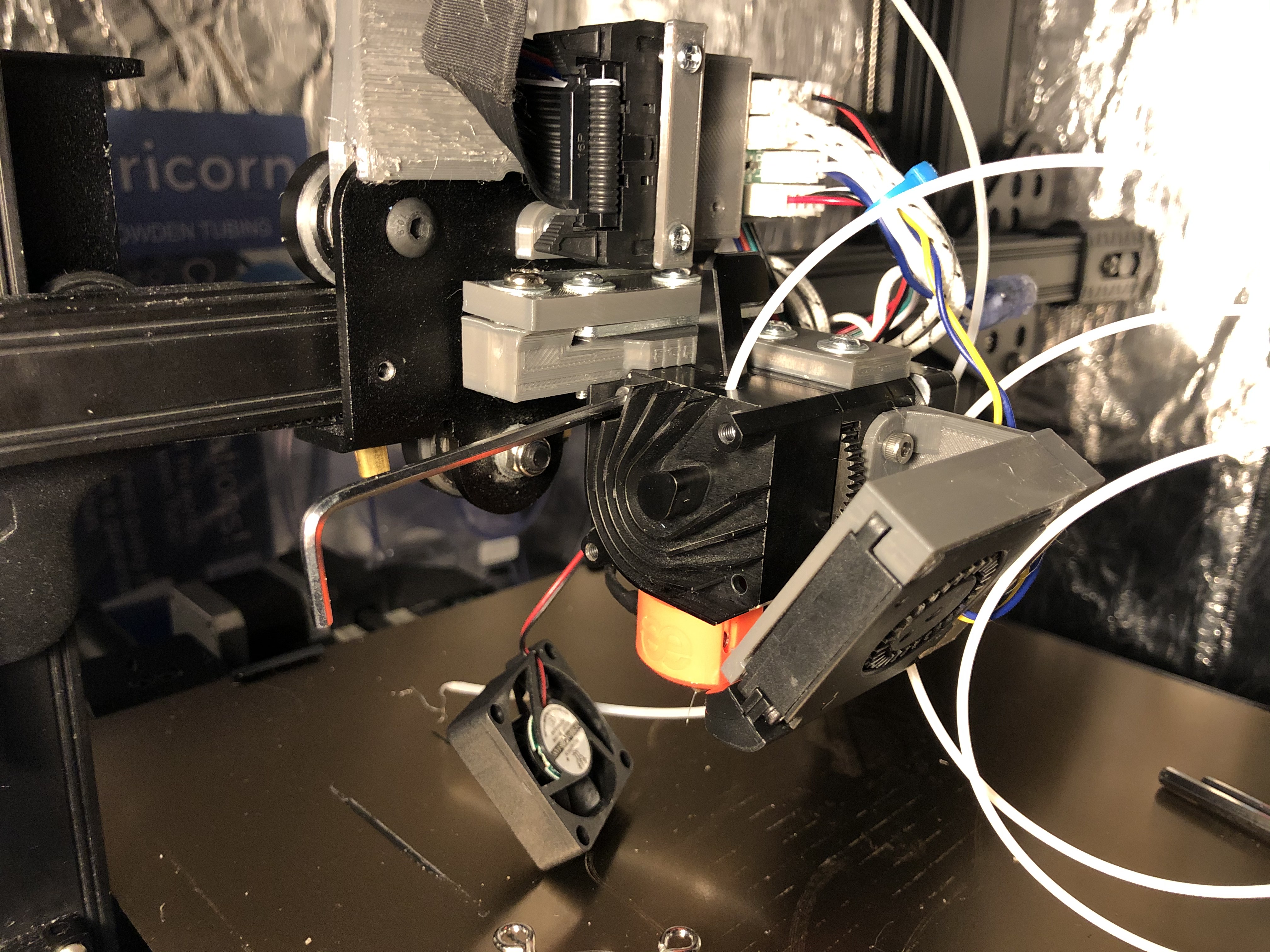
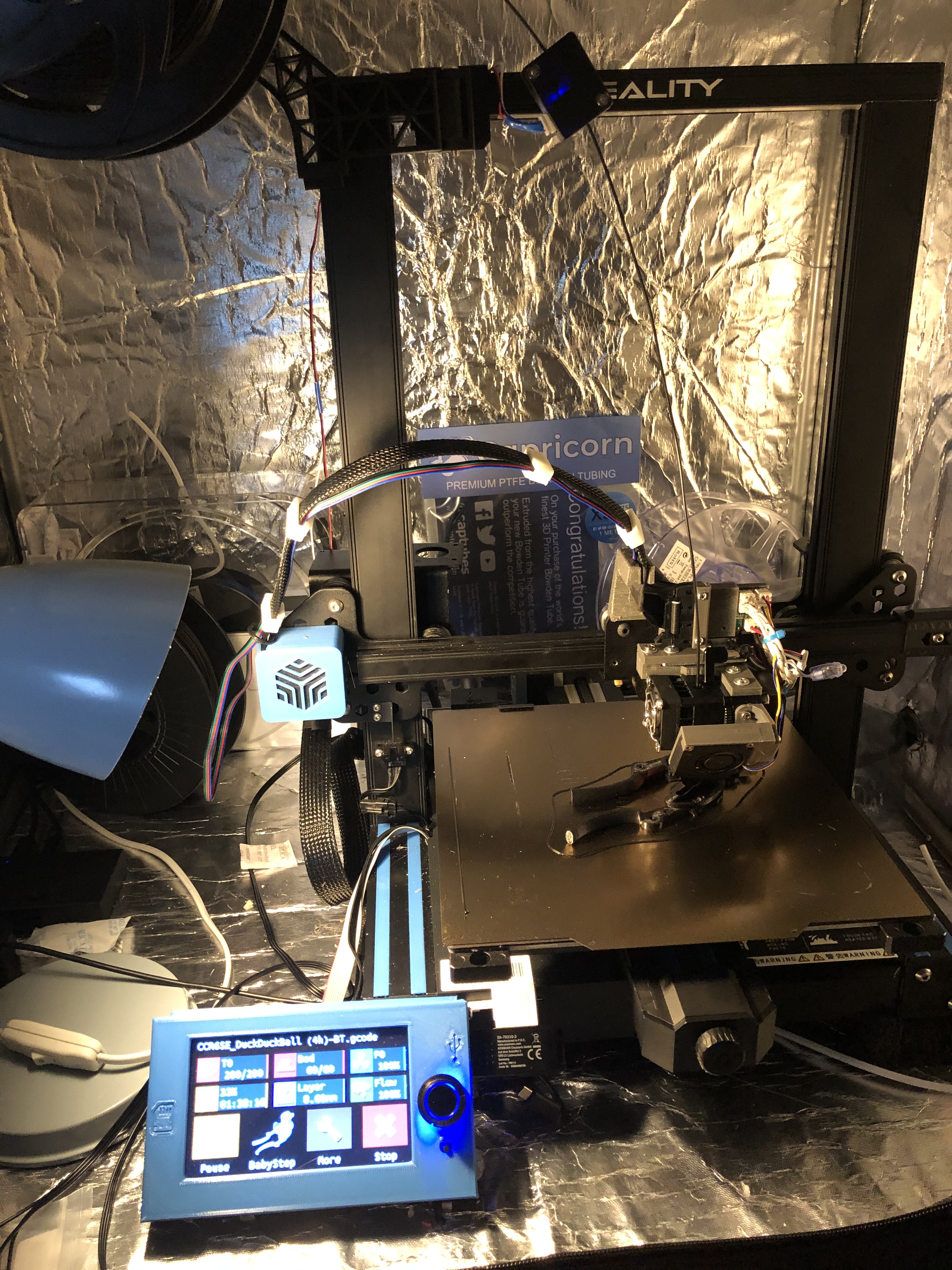 This is how the end result will look
We’Il start with a recap on the CR-6 bed leveling system, check what you need to have in stock or put in your shopping cart, print the parts and build the mod step-by-step.
The CR-6 SE bed leveling system recap
The Creality CR-6 SE homes and levels the bed using the nozzle - this system uses a strain gauge. What does that mean?
The hotend is hanging from a bendable piece of metal. That piece of metal has a conductor glued to it, which changes resistance when it is bend. The change in resistance is noticed by a HX711 chip. A piece of firmware written by Creality, that runs on a neighbouring STM32 32-bit (!) ARM processor, then processes the “weight” value that comes from it. If it is within a certain threshold, it tells the motherboard the Z-endstop is hit. That is how it homes and levels the bed. As a visual indication, the LED on the PCB is also turned on.
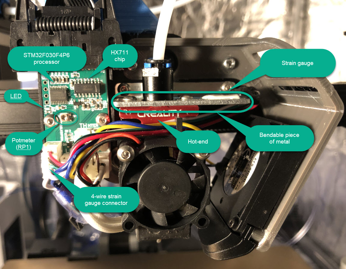
In the average digital kitchen scale a similar piece of metal and signal processing will exist - so just think of this entire system as a kitchen scale with a hotend attached to it.
Just like a kitchen scale, this system can be tared (or “zeroed”). That means that the current “weight” is taken as a zero value. This taring happens when:
- The printer is turned on
- When it is homing and the optical sensor on the gantry is blocked
- At every leveling point when auto bed leveling.
If you want to test it, turn off the printer, press the hotend up and while you do that turn on the printer. Let the hotend go, and you’Il notice that you need much more force to turn the LED on.
So, this leveling system is nice and when it works, it works very well - but it makes for a few extra steps when you want to mod your printer.
Tools and bill of materials
You’re going to need to buy a few tools for this, if you don’t have them already.
You need the following tools:
- A decent wire stripper. I used a Jokari 20050 - good German quality.
- Needle nose pliers and snipping tools
- A crimping tools with a die suitable for JST-XH connectors, for instance the Paron JX-D5
- Soldering iron or heat gun
You need the following materials:
- A set of JST-XH connectors. You’Il need several 2-pin connectors, two 3-pin connectors and one 4-pin connector
- A set of M3/M4/M5 nuts, bolts and washers. If you don’t have these already, just buy them. They come in handy in any 3d printing project.
- Two M4 threaded inserts
- Optionally some T-nuts for the filament sensor and spool holder
- Extended wires for moving the filament sensor
- Some zip ties to tidy everything up
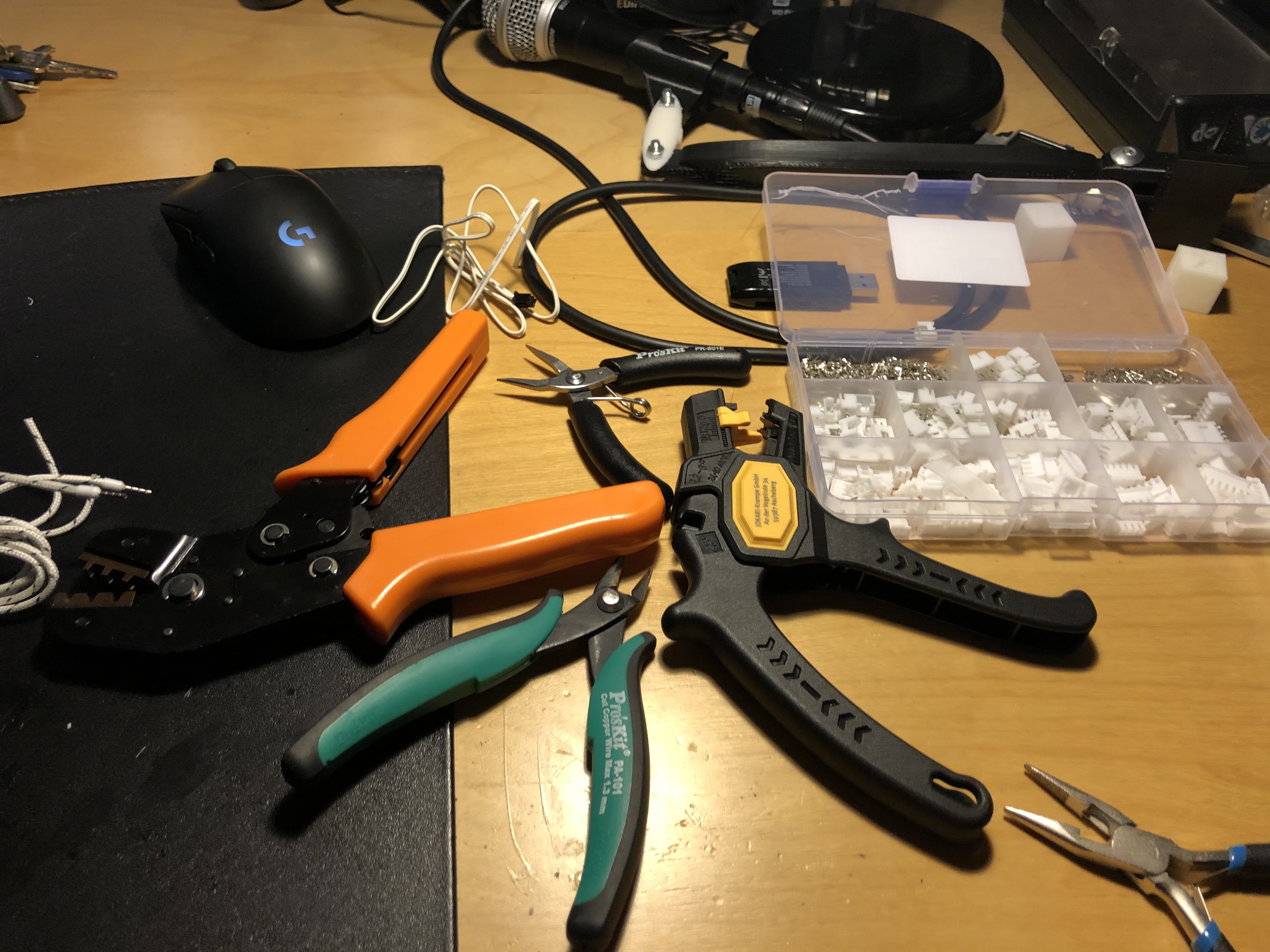 Just a handful of tools you are going to buy some time during your 3D printing life anyway
I would also recommend to have the BigTreeTech SKR CR6 motherboard installed on your printer. You’Il need it later to set the stepper motor current. On the stock Creality boards this can also be done, but it is more of a manual process. The CR-6 Community Firmware 5 beta or higher is also recommended because it allows you to change more parameters.
Preparing the printer
We need to calibrate the strain gauge and strip the X-carriage.
Strain gauge calibration
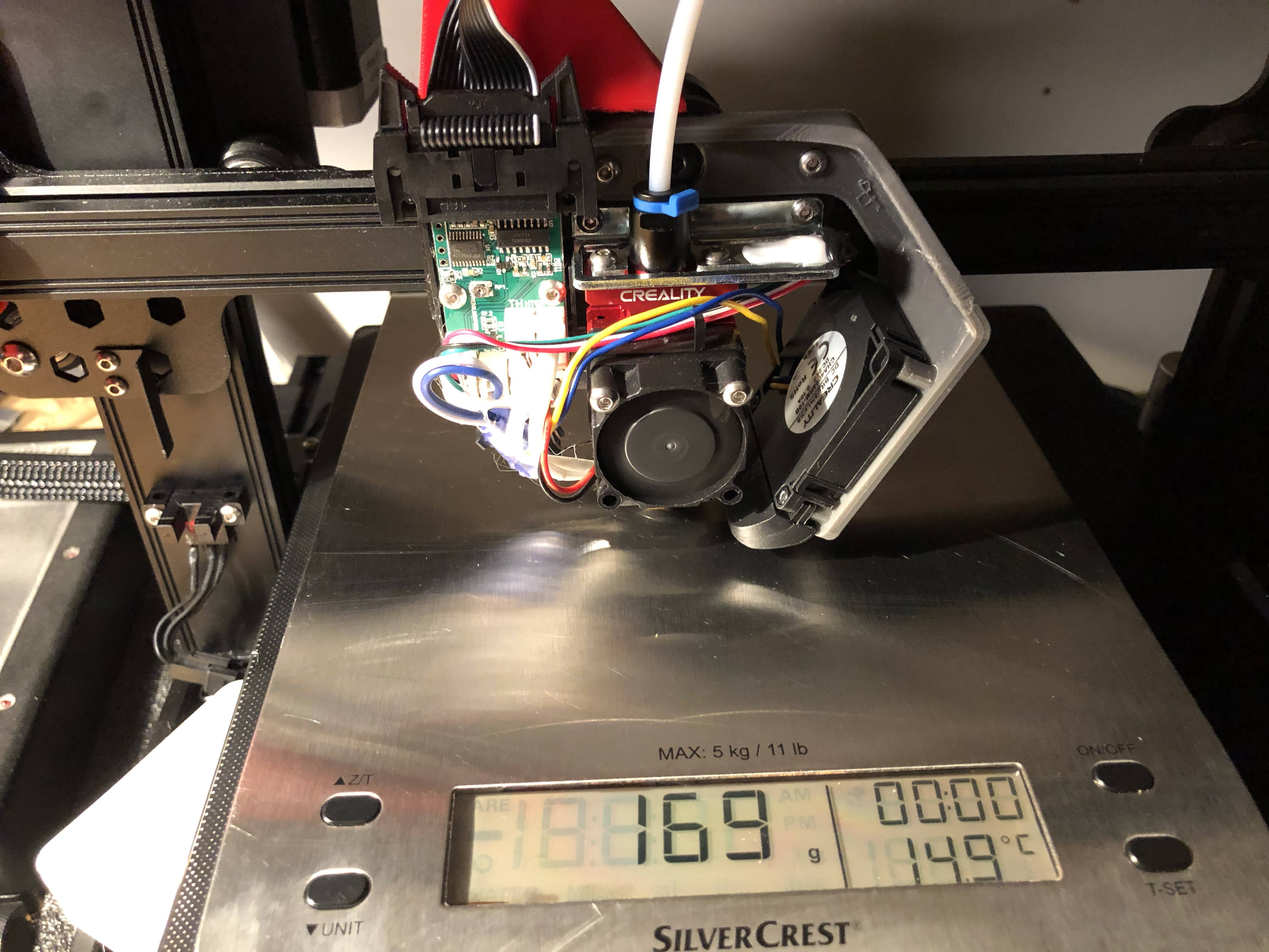
First we need to make sure the strain gauge doesn’t need too much force to trigger. The trick you can use is using a digital kitchen scale. You need to remove the fan shroud from the hotend, turn on the printer and manually (by turning the lead screw gently) move the Z-axis down.
Take note at what weight the blue led comes on. I did this trick on two printers and they each gave different results.
 160 grams is pretty okay
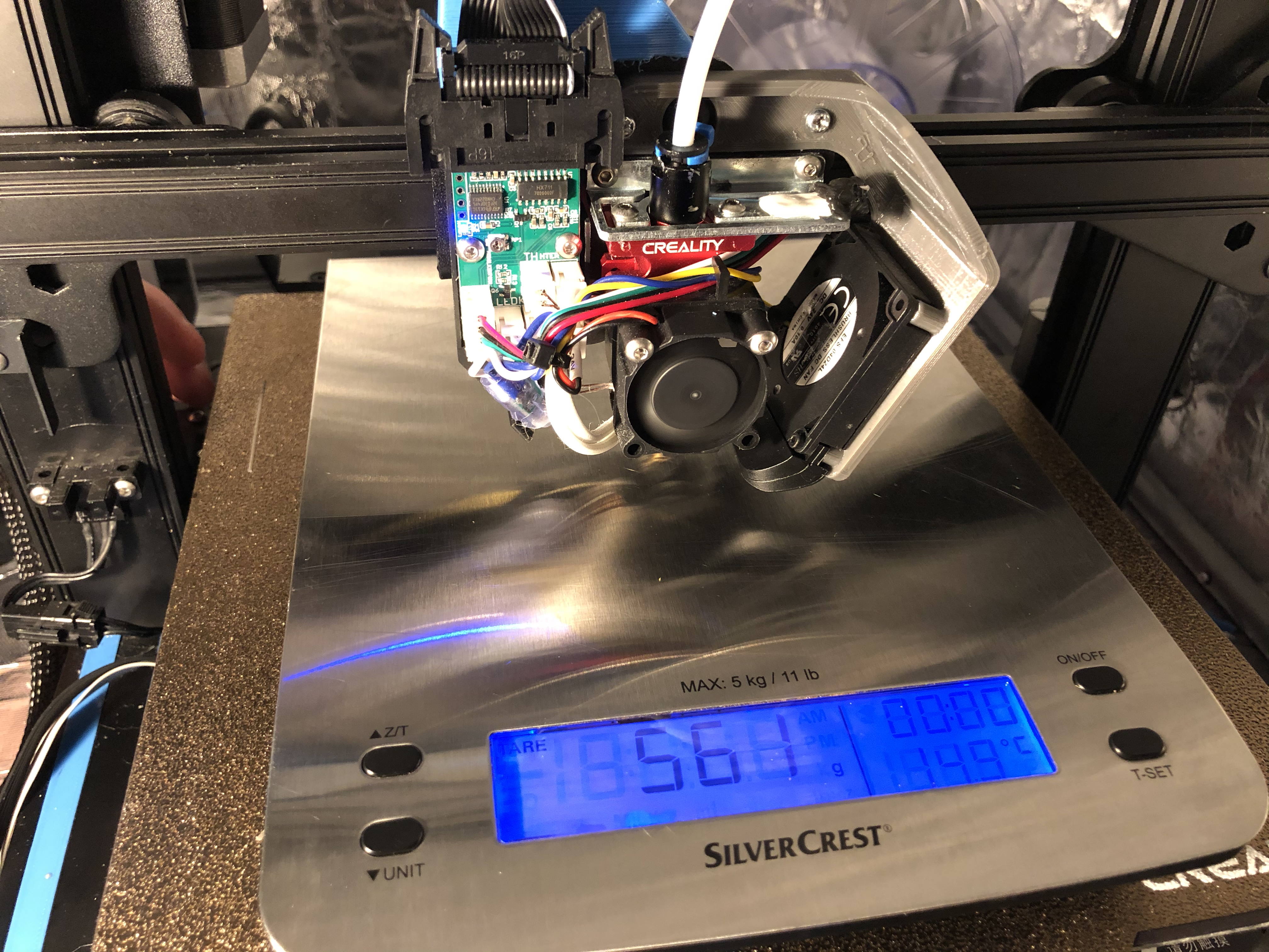 But I want to mount the DD to this printer, and over half kilogram of force is way too much!
To adjust the threshold on which it triggers, you need a screwdriver and turn the RP1 potmeter mentioned in the diagram a tiny bit counter-clockwise. Don’t turn it too far, this potmeter has no endstop and it will drop off the board if you turn it too far. The adjustments are very tiny and you need to turn the printer off and then on again to see the real result of your adjustments.
Calibrate it so it triggers at ~160 grams or less.
Stripping the X-carriage
You need to strip down the X-carriage to its most basic parts.
 The only thing that will be left is the strain gauge itself
For this, in order:
- Remove the bowden tube from the hot-end. You may need to heat the hotend up to PLA temperatures to remove it.
- Let the hotend cool down and turn off the printer.
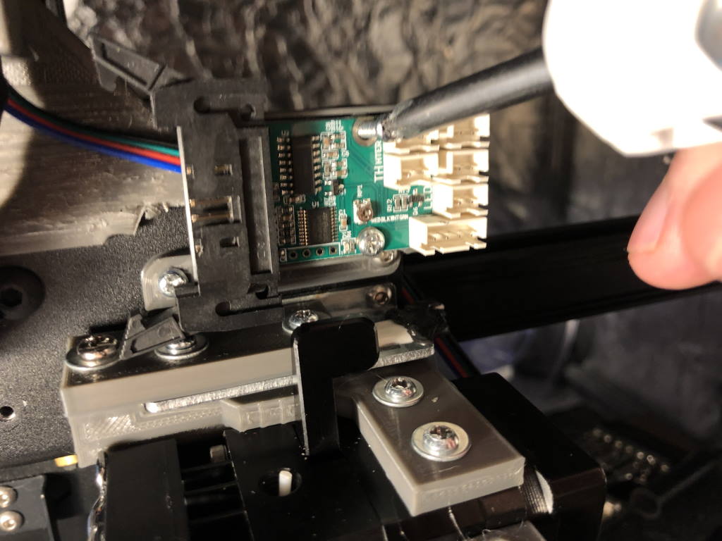
- Remove the fan shroud and the flatcable.
- The PCB near the hotend will be exposed. Creality loves hot glue, so soften it up a bit with a hairdryer or heat gun.
- Remove the hot glue from all the connectors. Do it gently. Make sure not to touch the PCB.
- Undo all the connections.
- Unscrew and remove the hotend itself.
- Unscrew and remove the PCB itself.
This leaves you with the strain gauge only.
Printing the parts
The kit has the following parts - all downloadable from Thingiverse:
- A mount for the direct drive extruder assembly itself
- A mount for the hotend daughter board (“strain gauge board”) PCB
- A mount for the filament sensor
- A mount for the filament spool holder
- A cable guide for the stock flatcable and wires for the stepper motor - I remixed that from this excellent design
- Cable clips designed to accomodate the flat cable and stepper motor wires
- A part cooling fan mount
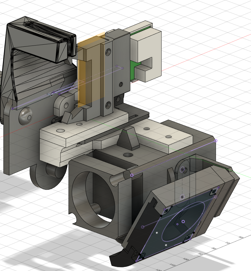 Basic overview of the different parts
 Filament sensor mount
We’Il go over the parts one by one and also assemble them. I have printed all these parts on the Creality CR-6 SE, with a BTT board, stock hotend and CR-6 Community Firmware 6 prerelease. During development I used Creality PLA, and for the final parts SUNLU PETG. If you are not going to print the parts on a Creality CR-6 printer or you are unsure of the dimensional accuracy of your printer you may want to print a draft in PLA first.
Direct Drive Mount
Let’s start with the most critical one - the mount for the BIQU H2 direct drive extruder itself.
This part consists of two parts:
- A part that you mount to the direct drive extruder itself
- A part that you use to sandwich the strain gauge metal between the mount
The idea is that for the normal printing we don’t want to have the entire weight of the direct drive hanging from that little piece of metal all the time. Especially X-moves accelerations might cause issues there. So what the direct drive “sandwich” does: it allows force from the bottom up - so the strain gauge can still trigger - but it does not allow gravity to pull the whole assembly down.
Print instructions: Print this with 4 or 5 wall count, 40% infill, and two infill lines for increased stiffness. I used gyroid infill for this. You need to have supports.
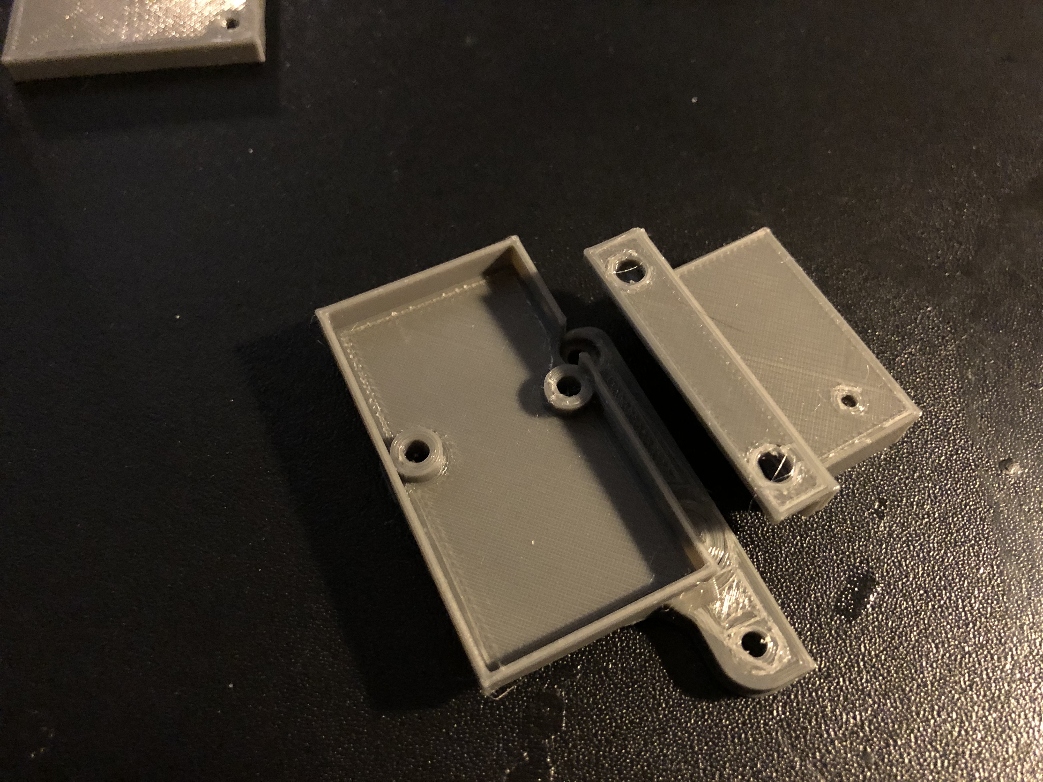
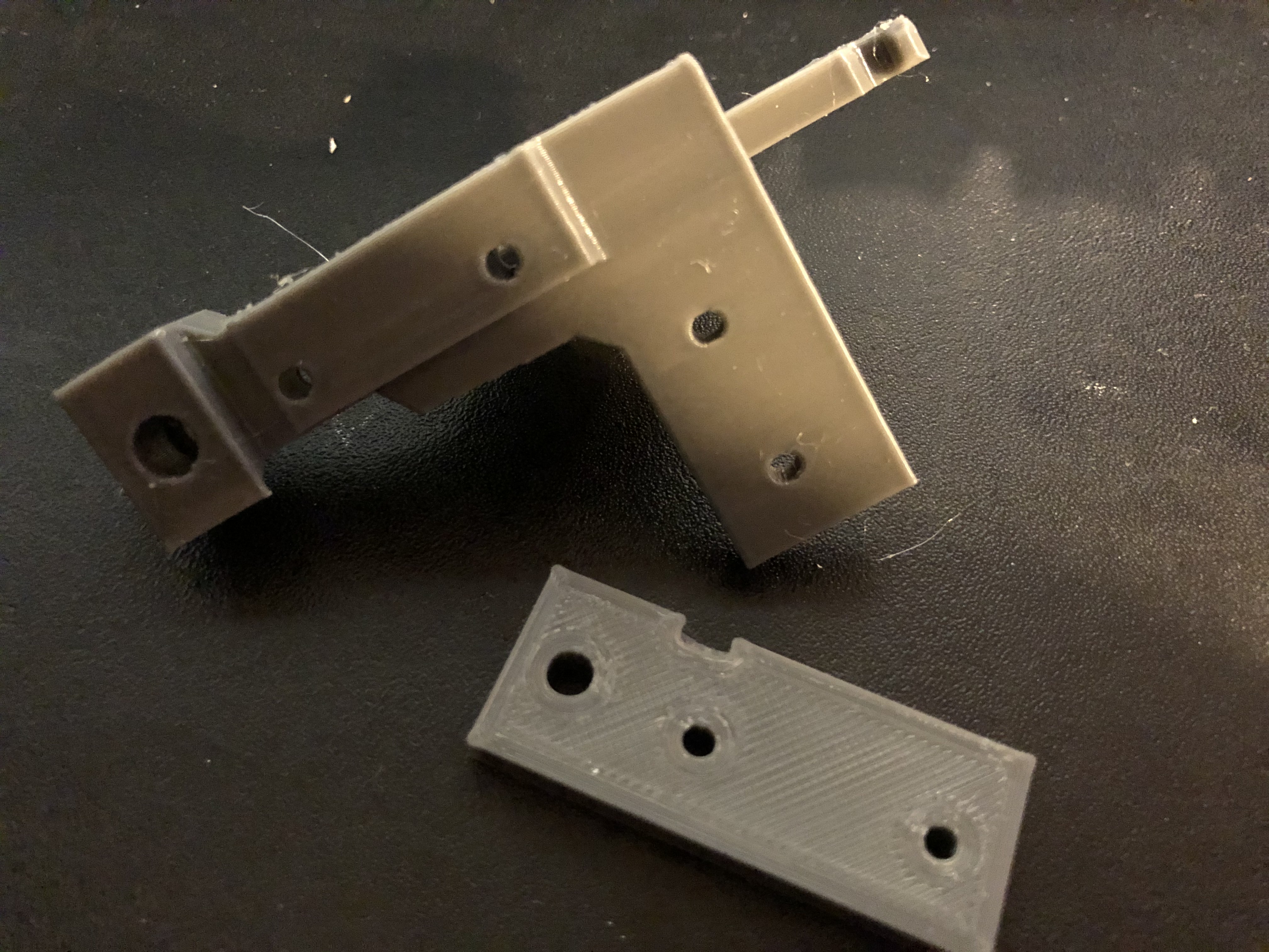 The parts of the sandwich
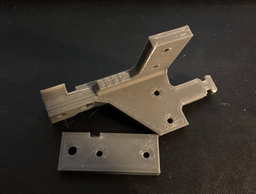 From another angle
You can already start inserting some bolts with washers. The bolts will have a little resistance when you screw them in, but not too much.
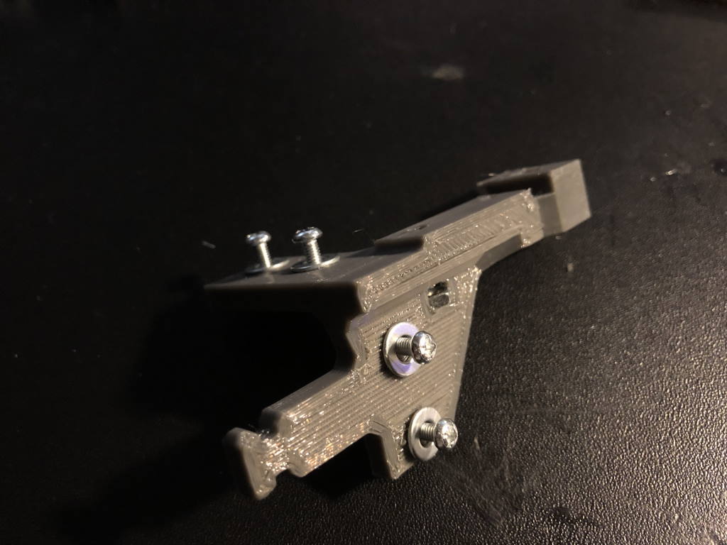 With some M3 bolts and washers
 Mounted to the direct drive - at the top side and at the back side
You now need to heat up your soldering iron or heat gun. One of the metal inserts that will be used for sandwiching (is that even a word?) will need to be pushed into the printed part.
 Heat it up a bit and you can press it right in
 Metal insert… inserted
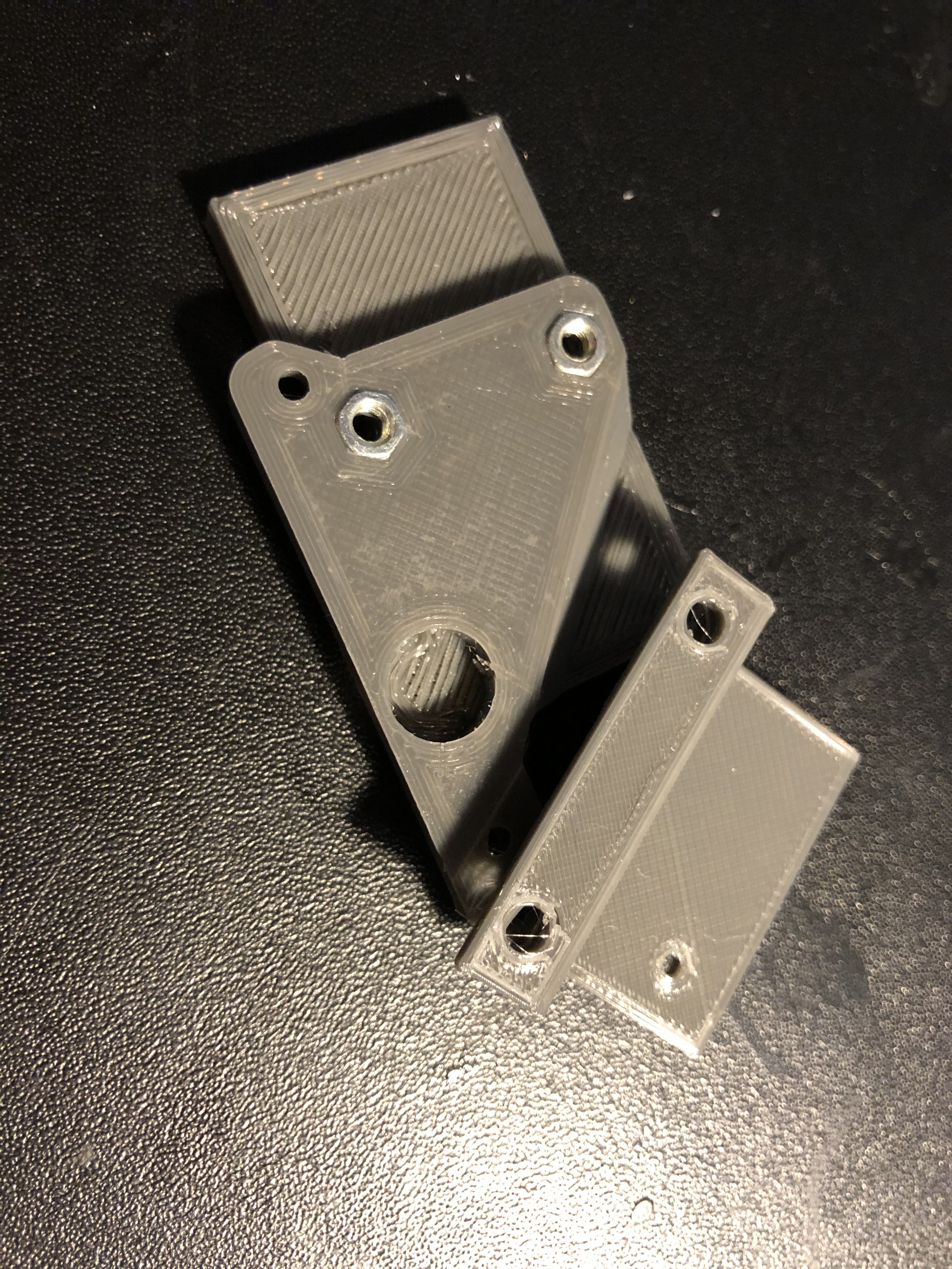
I didn’t have M3 metal inserts in stock, so I provisioned some space for M3 nuts.
 Insert the M3 nuts into the pockets - the nut on the left may be too loose and you may want to use some tape to hold it in place. The nut on the right should friction-fit.
That’s it for the direct drive mount, for now.
Filament sensor
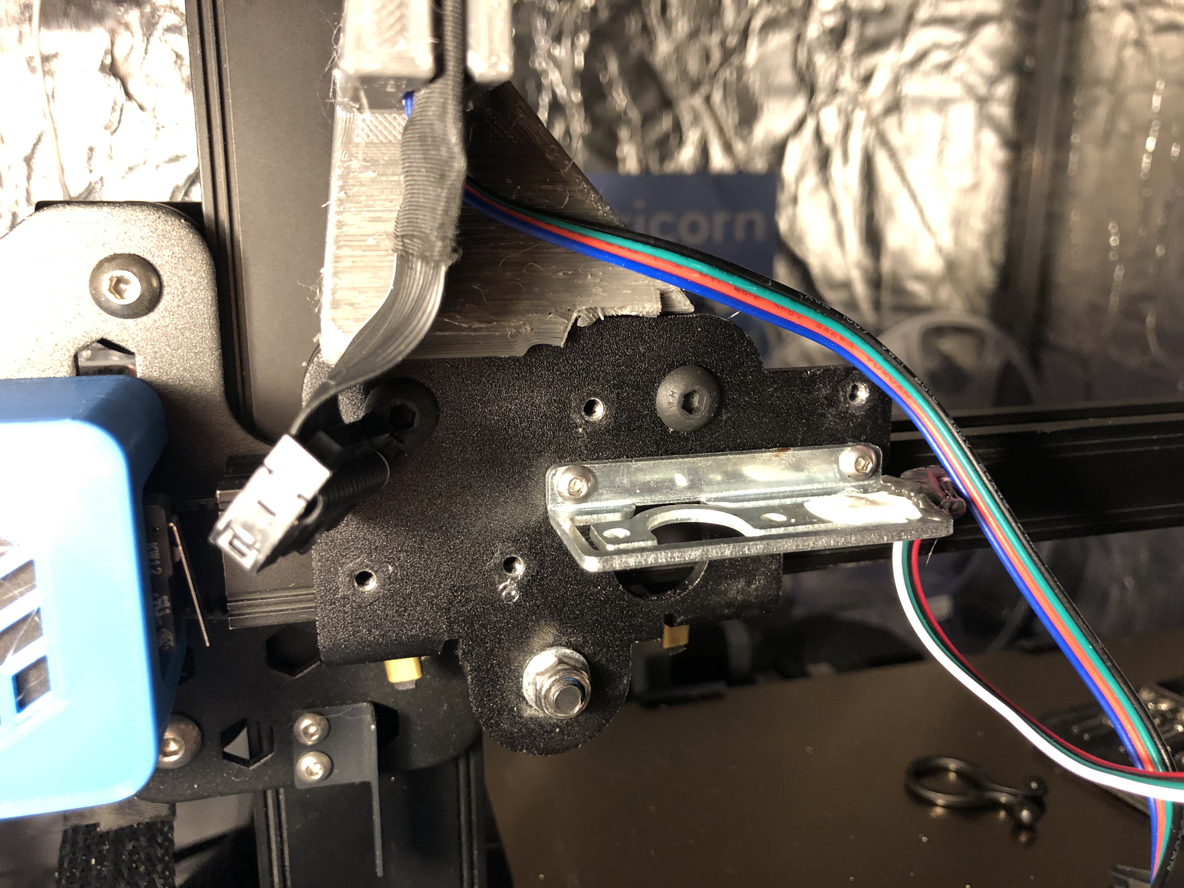
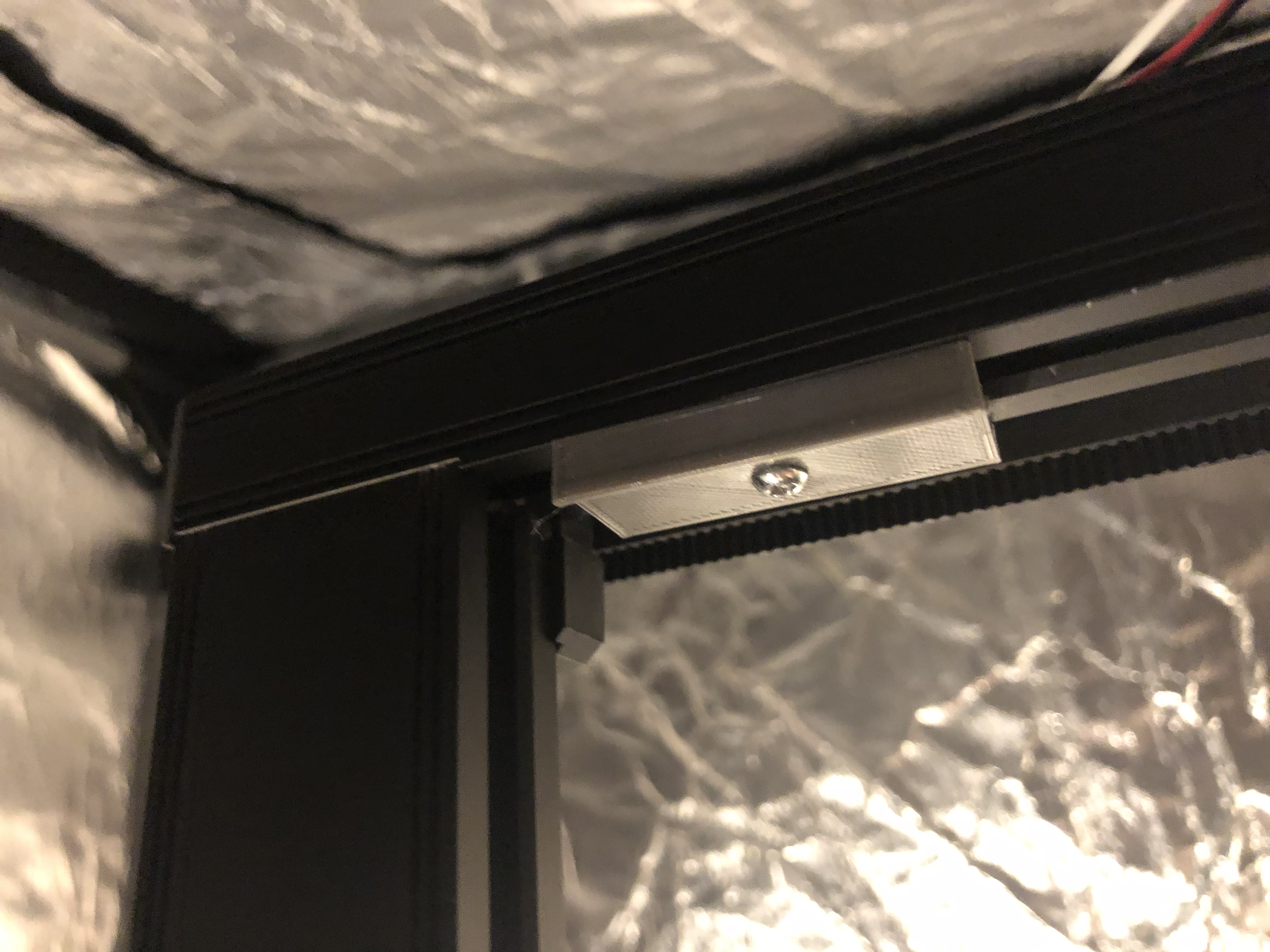
The filament sensor will be mounted at the top of the gantry. It uses a metal insert as a hinge so it can rotate as the X-axis moves.
Unmount the filament sensor from the X-axis and keep the screws.
Print instructions: Print settings don’t particularly matter - not much force will be on this
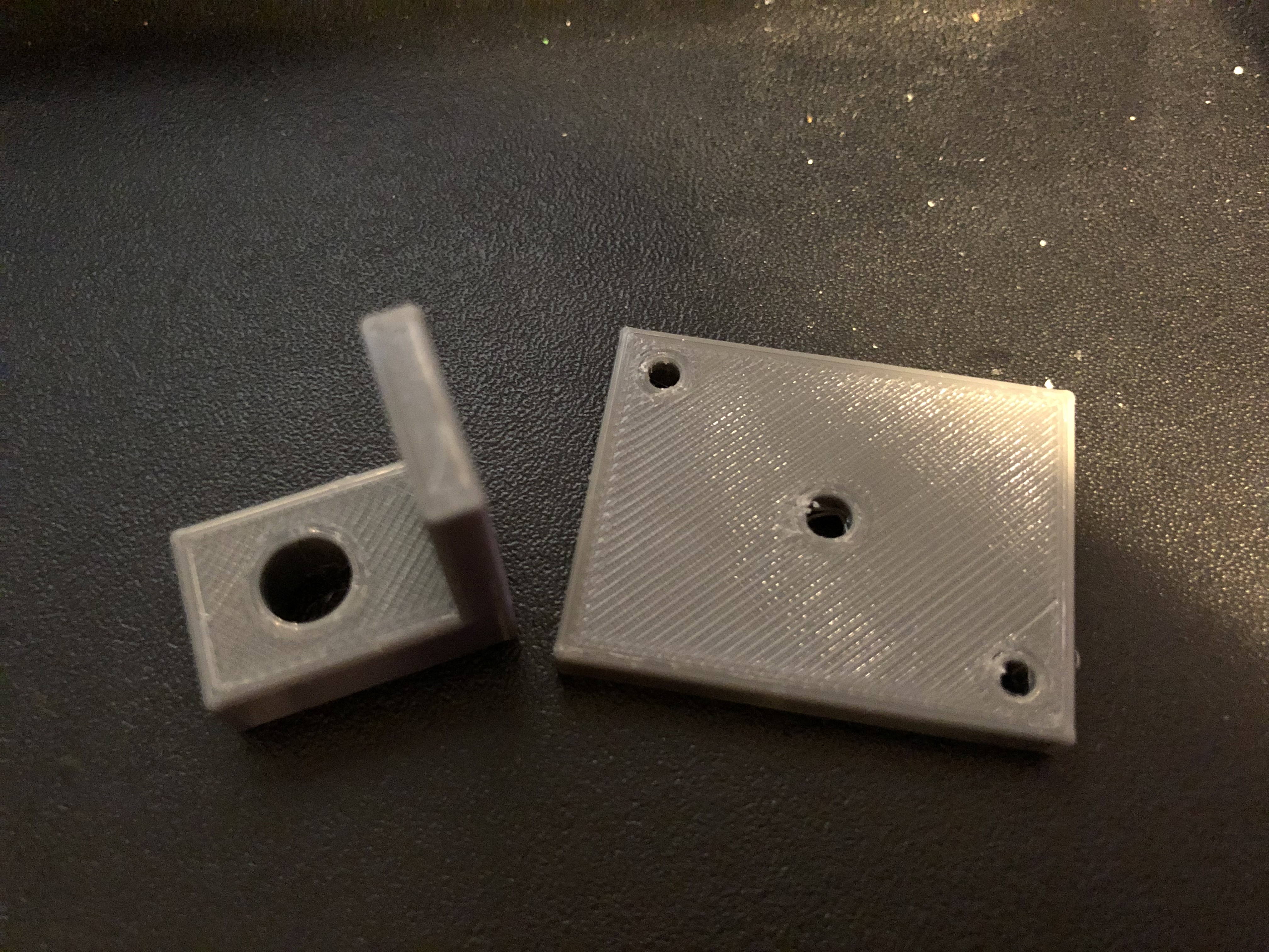 The two printed parts - the 90-degree angled piece will go on the 2020 aluminium extrusion, the plate will have the filament sensor mounted to it
 Insert the metal insert while its hot
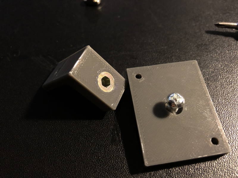 A M4 screw will be used at the filament sensor base plate - note that there is a recess so the screw head can fit properly
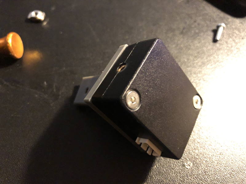 Everything assembled - except for the T-nut at the top-left of the picture
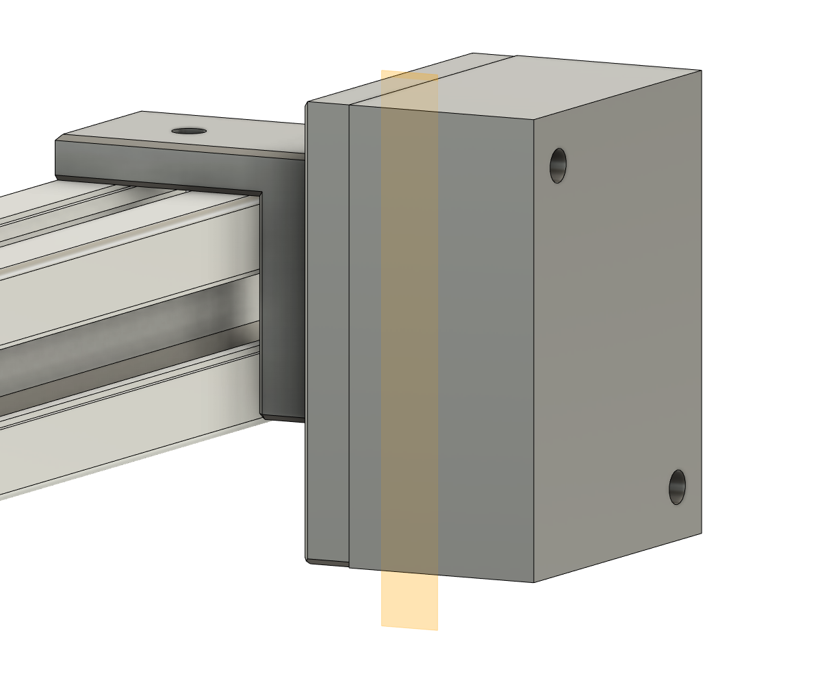
Spool holder
The idea of the spool holder is that you can re-use 100% of the stock spool holder. A printed piece will provide a way for the bottom of the spool holder to clamp to the extrusion. Alternatively, you may want to print a complete spool holder - like this top mount spool holder.
Print instructions: I printed this part 100% solid
 This works fine for 1kg spools - you probably don’t want to hang more weight to this construction though
You need a T-nut to clamp this assembly in place and can them slide the stock filament holder over it.
Cable guide and cable clips
Follow the instructions on the original for print settings - but use the model I provided. It is remixed so it fits together with the PCB cover and provides some space for the stepper motor cable.
You need to print about 4 or 5 cable clips.
Print instructions: I printed these all solid
Hotend “strain gauge” PCB mount
The hot-end PCB accepts a flatcable and breaks that out into a few connectors. It also houses the electronic components necessary for the strain gauge to function. This printed part will mount it directly to the X-carriage and also cover up the components.
Print instructions: I printed this using default settings - but with supports
 PCB mount and the cover
 You need to press in two M3 nuts - those will hold the PCB in place against the mount
 After this, you can screw the cover in place on the X-carriage
Cooling fan mount
The cooling fan mount uses the standard cooling fan and its “mouthpiece”. There are also several alternative nozzles available for the CR-6 fan. They should all fit, provided they are mounted inside the outlet of the fan.
Print instructions: I printed this using default settings
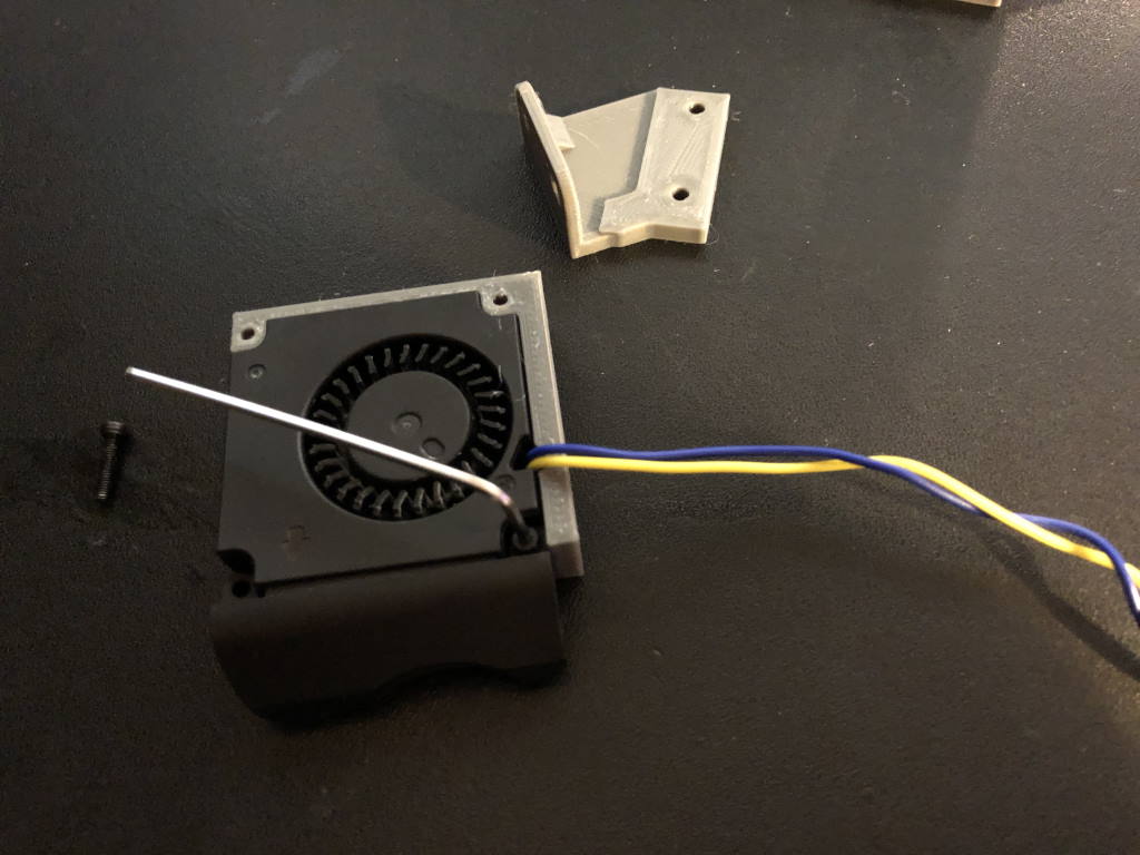
The fan mounts to the two front M3 screw holes on the front of the extruder.
Mount the fan with the original screws into the holder. Mount angled mount to the direct drive, and finally mount everything together.
Crimping the cables
Crimping the cables is the most pain. When you don’t have much experience with it, make sure you view several different YouTube videos first on how to do it. I didn’t have much experience with it but eventually I got the hang of it. I’m sure you will too. Make sure you leave enough room for mistakes.
You need to crimp at least the following cables:
- Hotend cable - this one has ferrules by default but we only have a JST-XH connector on the board. This is a bit tricky to crimp. Make sure for the part where you crimp it you remove the outer cotton layer and only crimp on the inner plastic shell.
- Filament sensor cable - crimp a new long (30-50cm) cable for this or buy one seperately
Highly recommended to shorten and crimp these cables:
- Thermistor cable (2-pin connector)
- Hotend cooling fan cable
Also recommended to crimp:
- Extruder stepper motor cable - this one has a dupont connector at the other side. It fits and works but may come loose due to vibrations. You can put some hot glue on it because that is a theme with this printer, but you have been crimping cables anyway so you might as well do this one too. Before you crimp this cable, make sure you have the right orientation so the motor moves in the right direction. If you don’t do this it isn’t a big issue, but you would need to recompile the firmware.
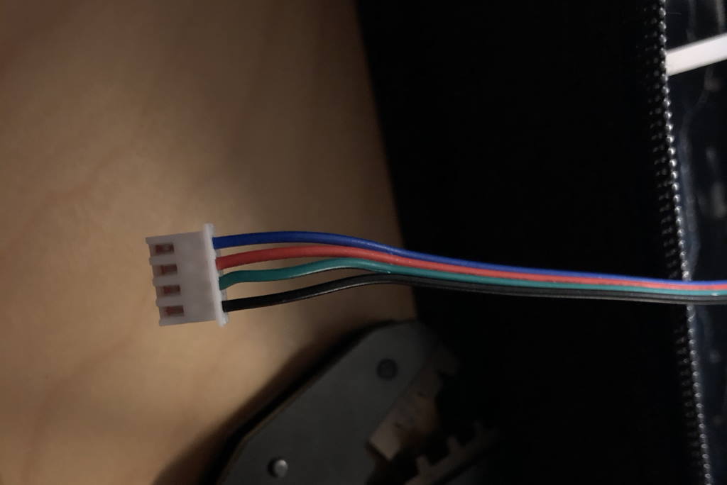 The extruder stepper motor cable crimped - after you’ve crimped the cable the wires should not be able to move out of the connector. When in doubt, start over.
 The new stepper motor cable and filament sensor cable go to the breakout board
Mounting the direct drive
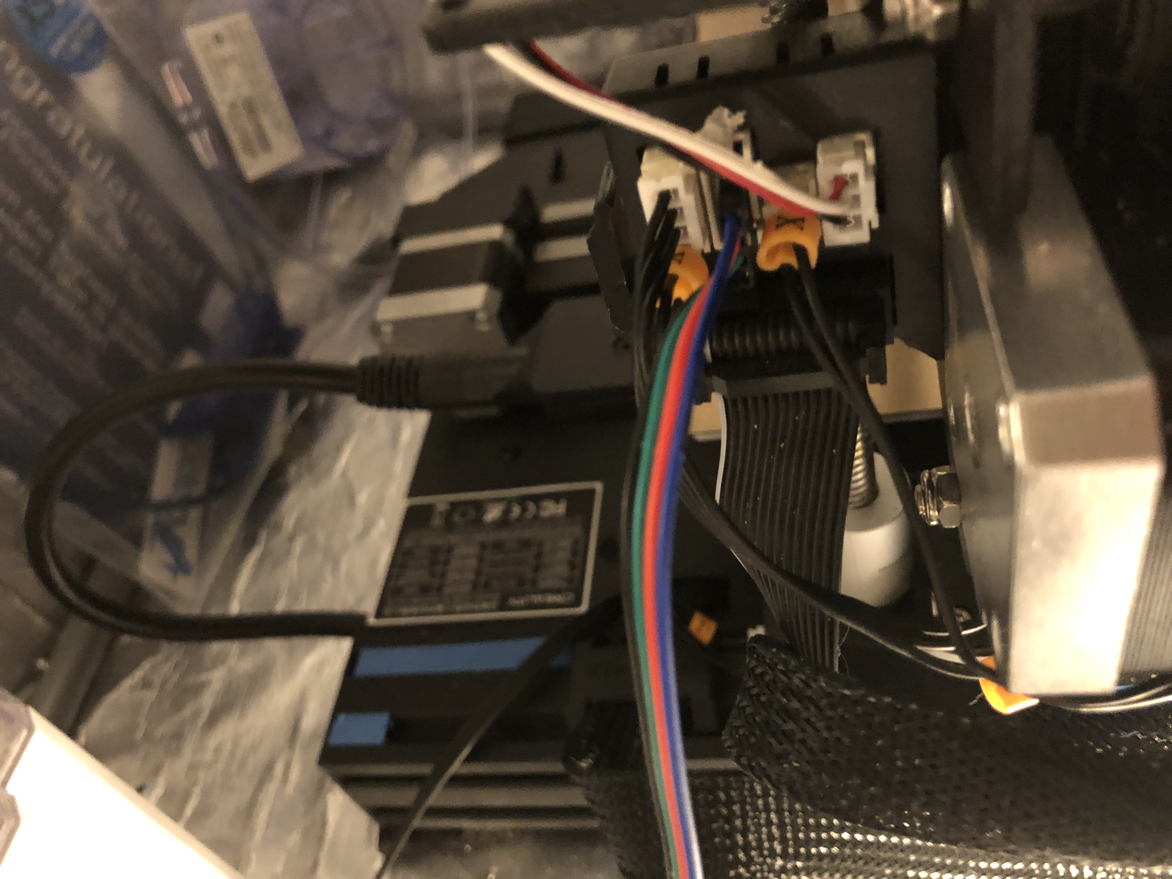
Start by installing the cable guide and routing the main flatcable and stepper motor cable through it.
Mount the direct drive to one of the bolts on the strain gauge metal, then mount it to the bolt next to it.
 Note washers are also used here. Don’t forget the upper part of the sandwich
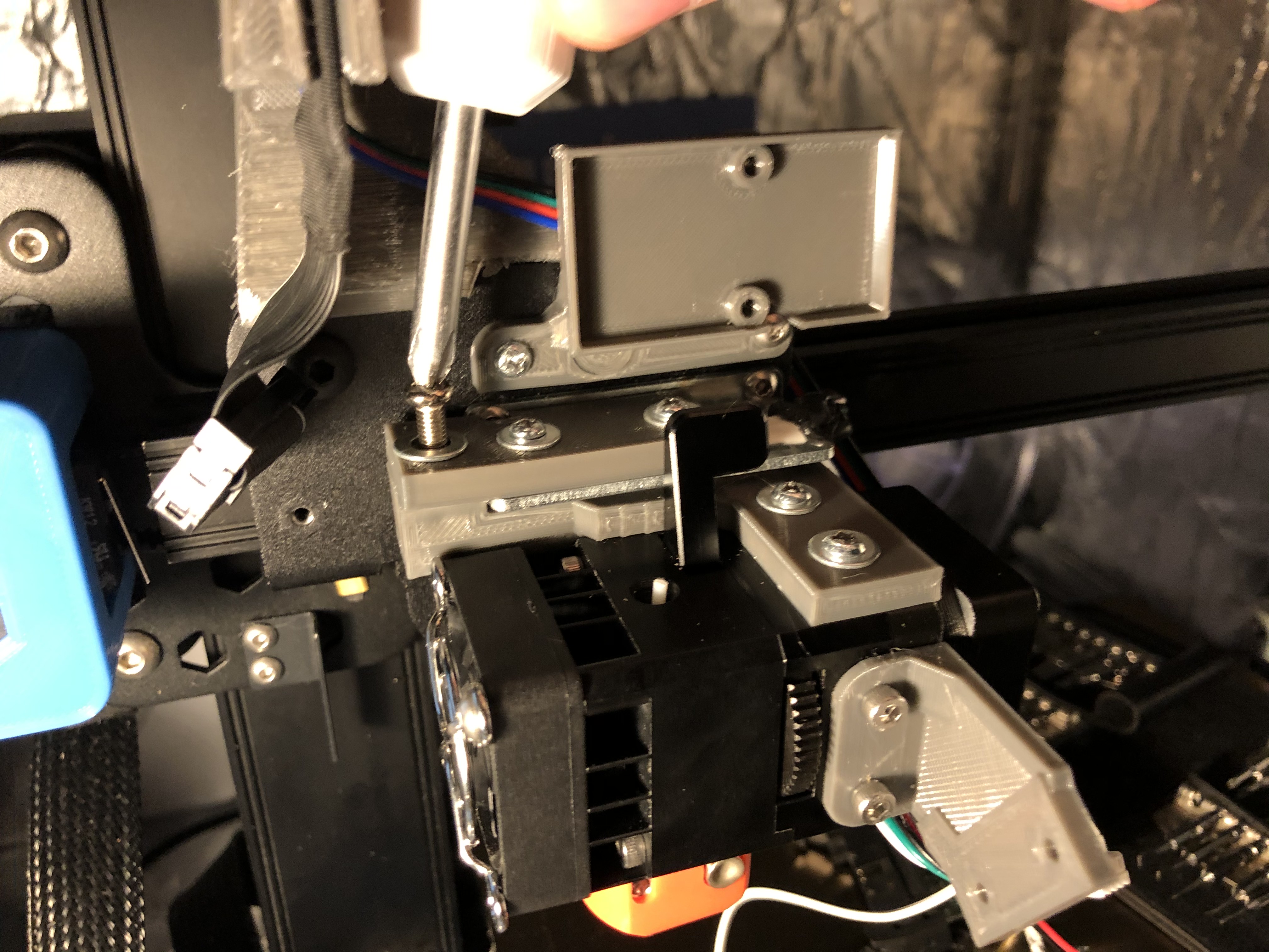 The M4 bolt tightens the direct drive sandwich
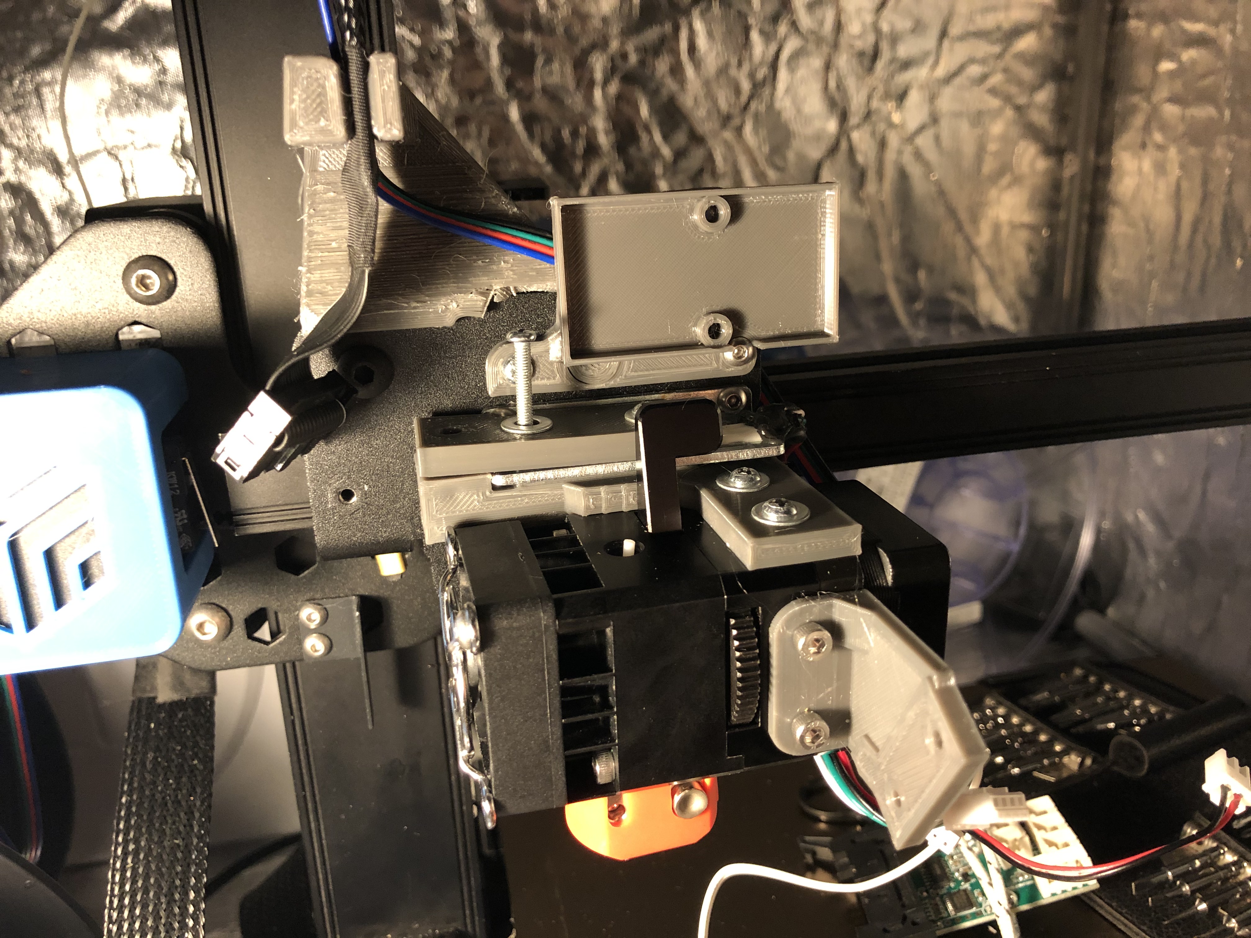
 Part cooling fan installed
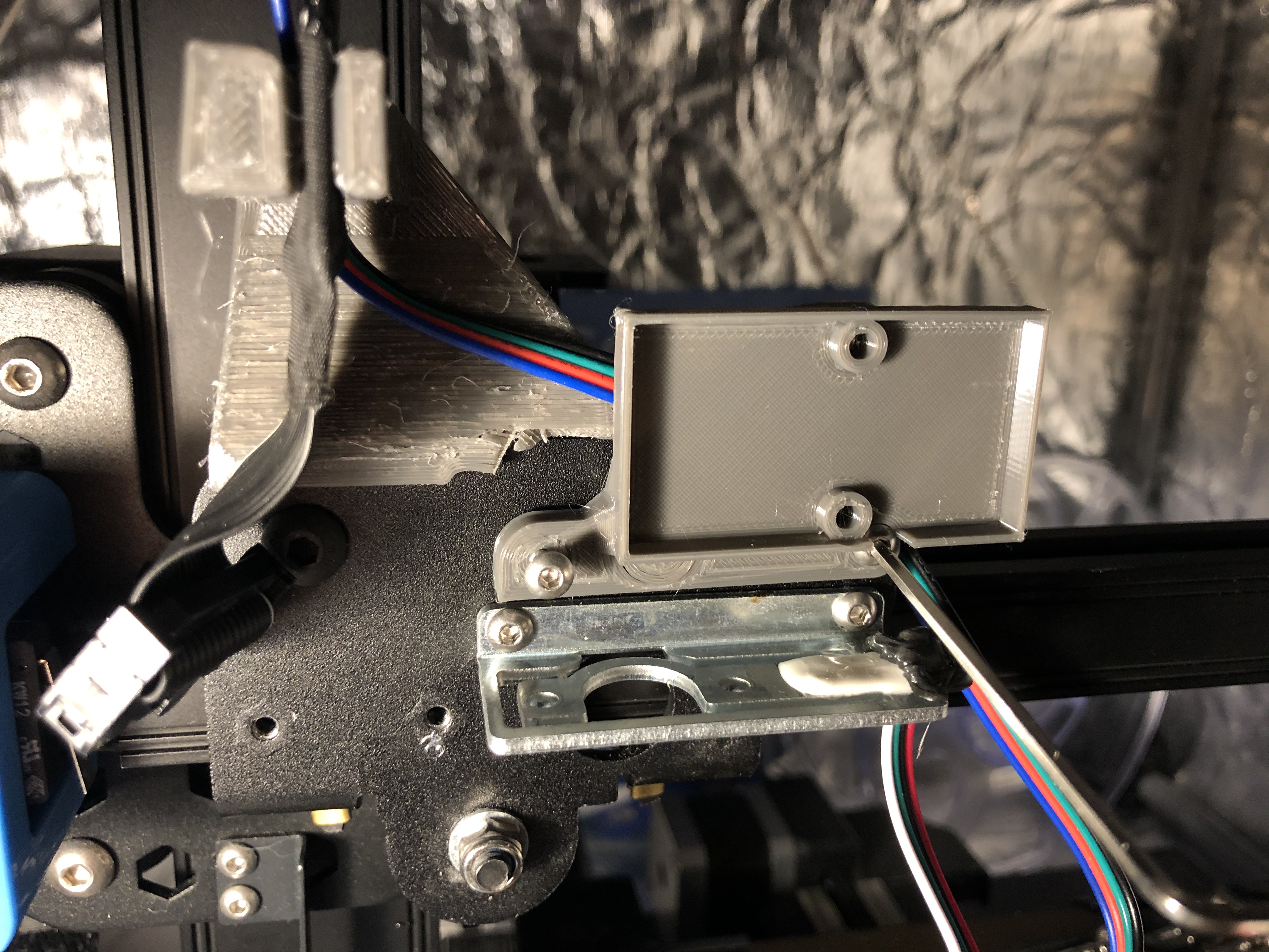
 Mounting the PCB
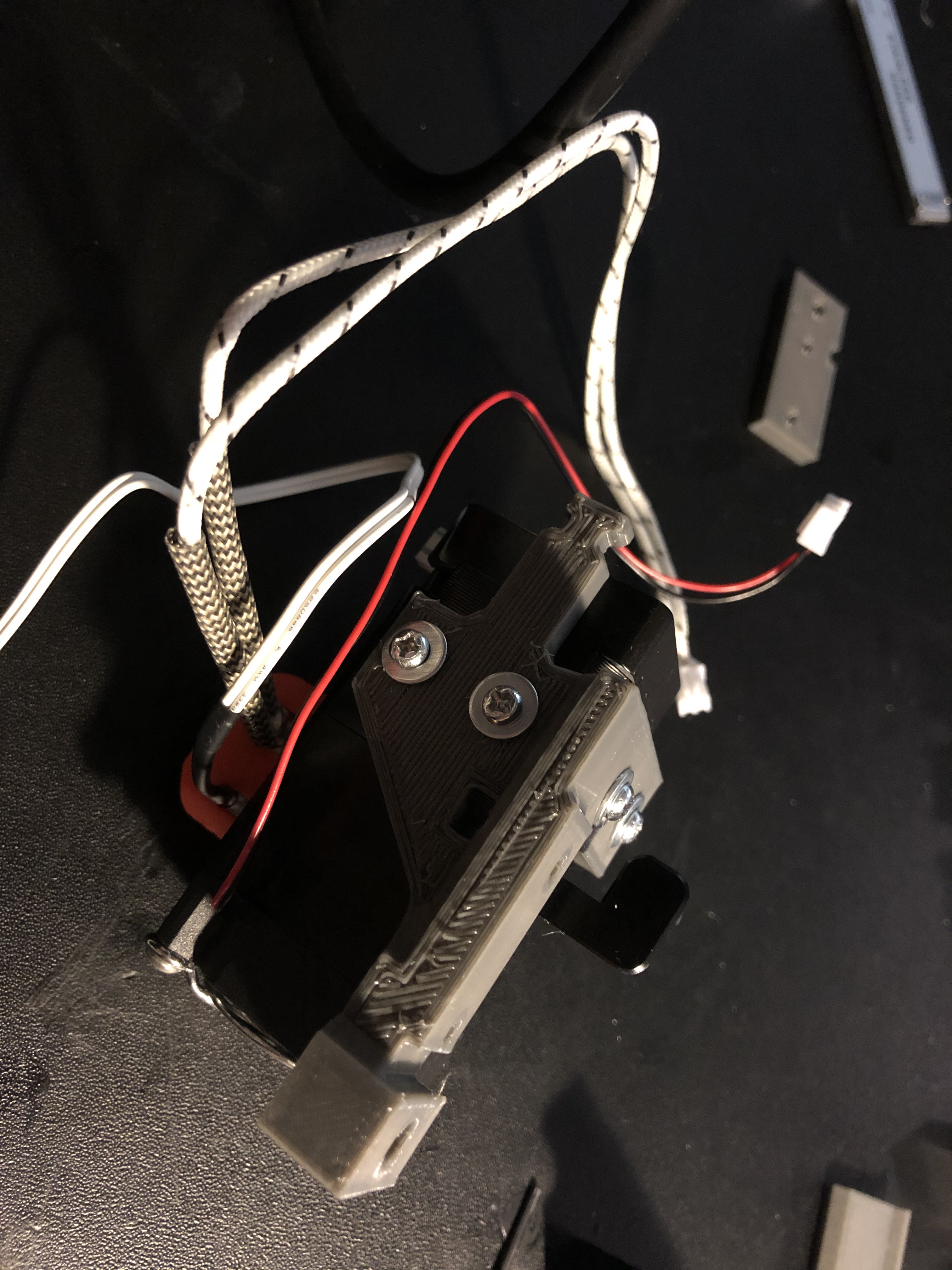
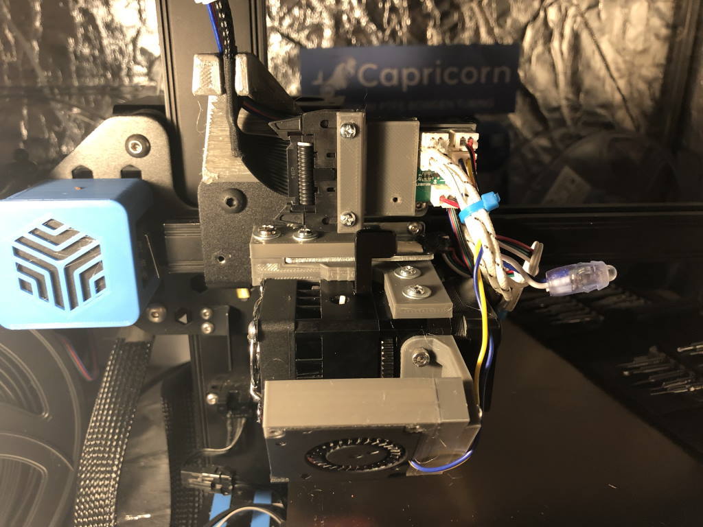
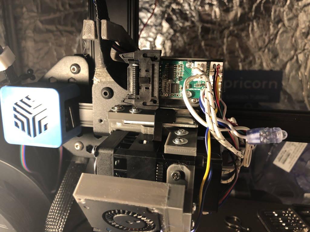 Wiring it all up
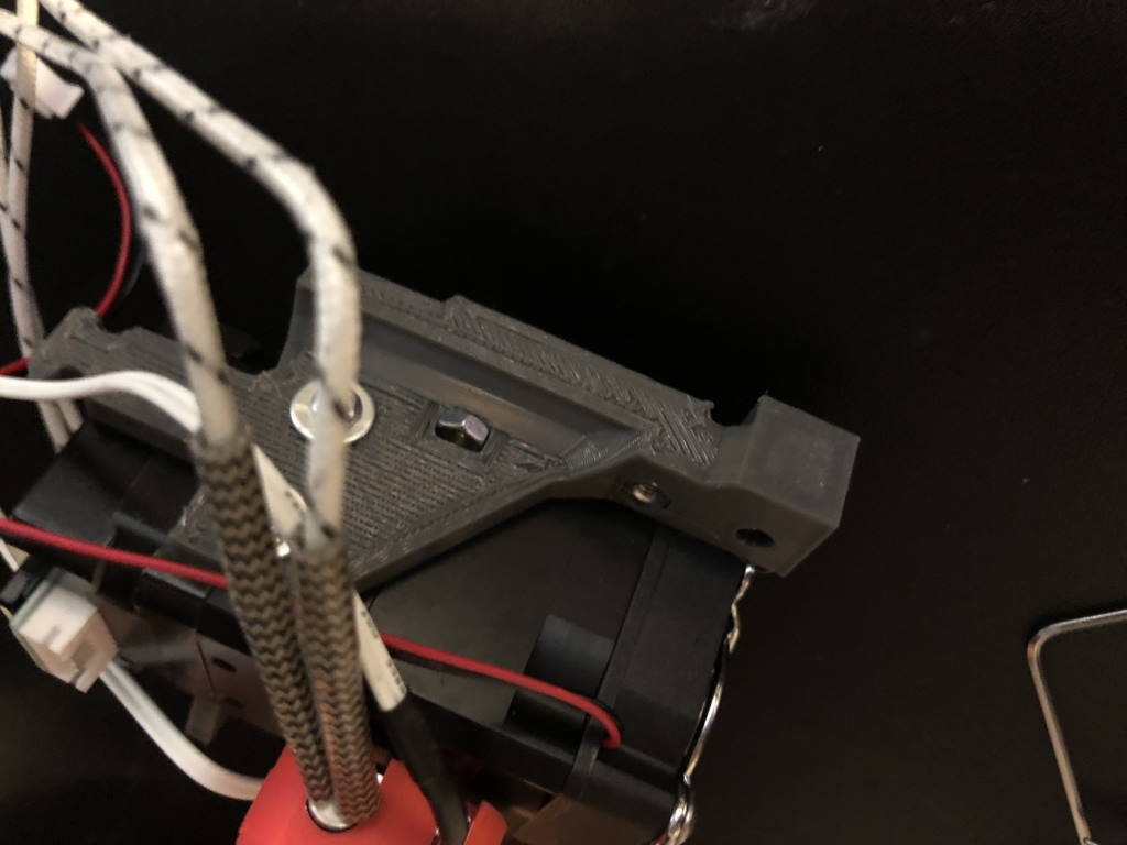
Finally mount the PCB cover. The part on the left will go with some screws into the cable receptable. There is a small hole in the mount - this allows you to see the LED of the hotend board.
 And now that ugly PCB is out of view
How to do maintenance
With my limited design skills, I still tried to make this easy enough to maintain. To get to the extruder gears you don’t need to remove the entire assembly - only a part of it. You may optionally want to remove the part cooling fan before you disassemble it, but it is not required.
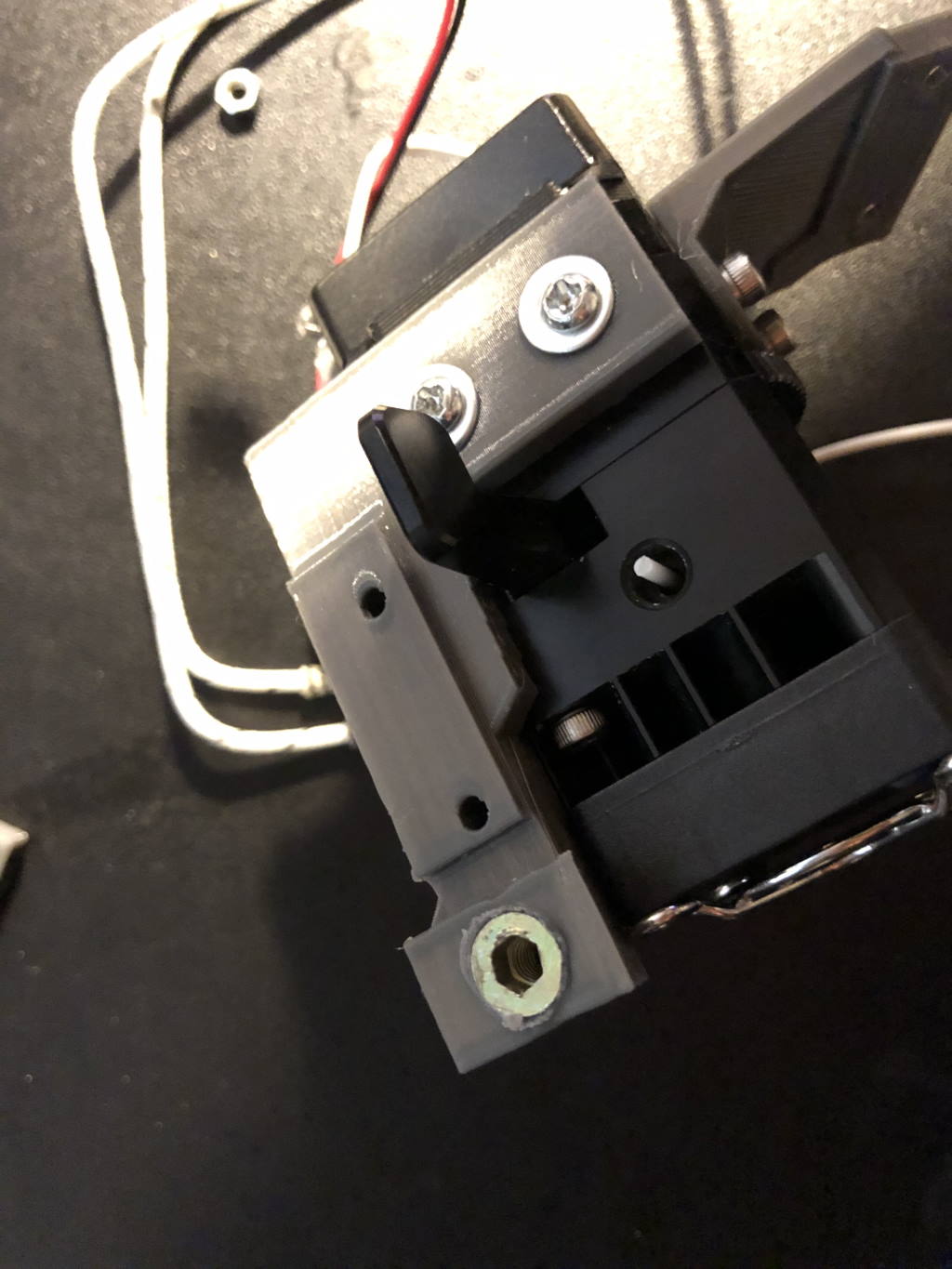
 Remove the hotend fan, then undo the long M4 bolts that hold the direct drive assembly together
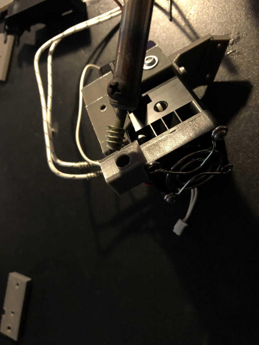
Now the bolts are removed you can press the lever to untension the extruder and use a little force to take the assembly apart. The tiny bearings inside the extruder may pop out, make sure not to lose them!
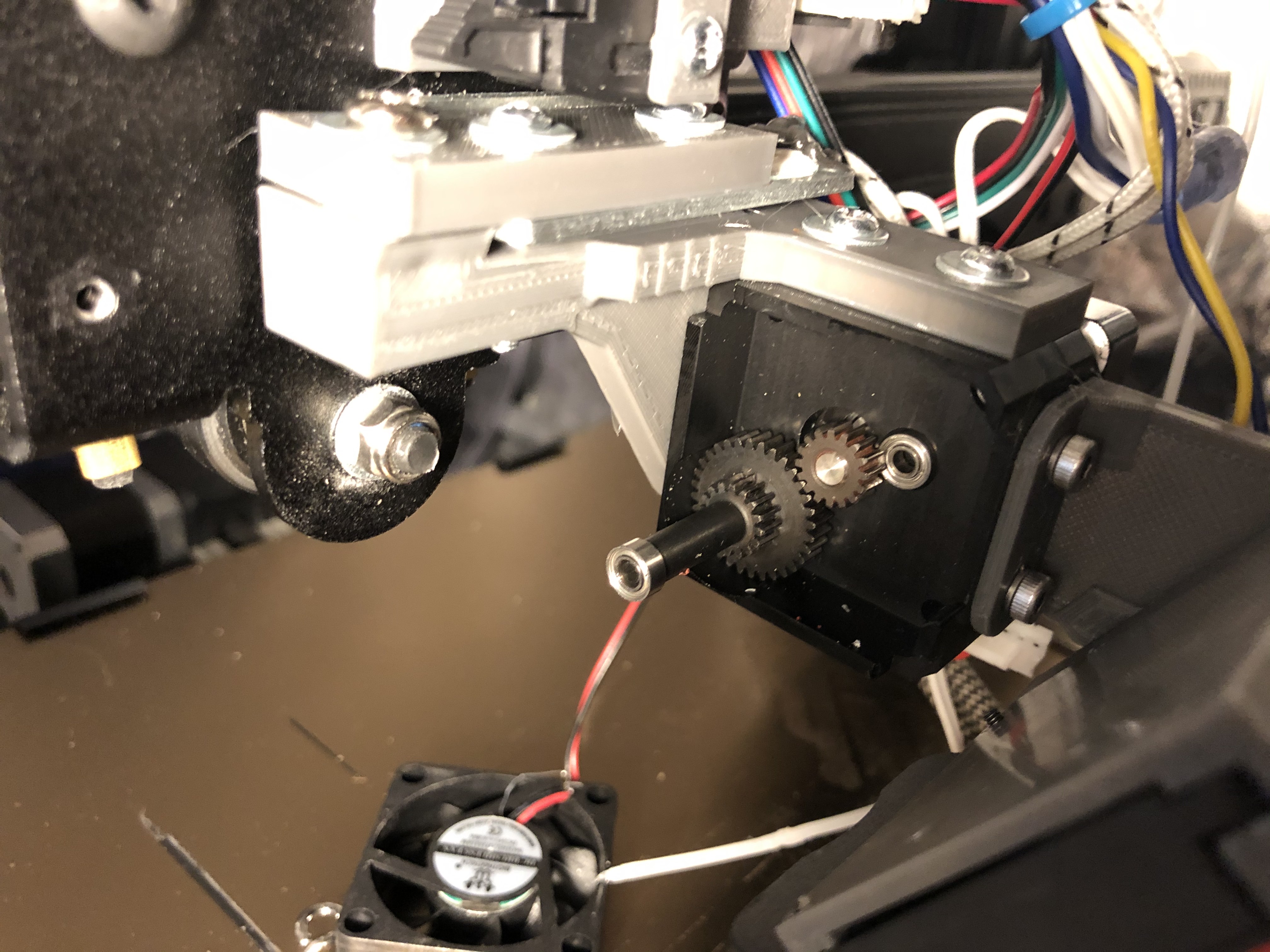 And gone is the hot part. This is the stepper motor gear and the first step-down gear. Note the tiny bearing on the right side.
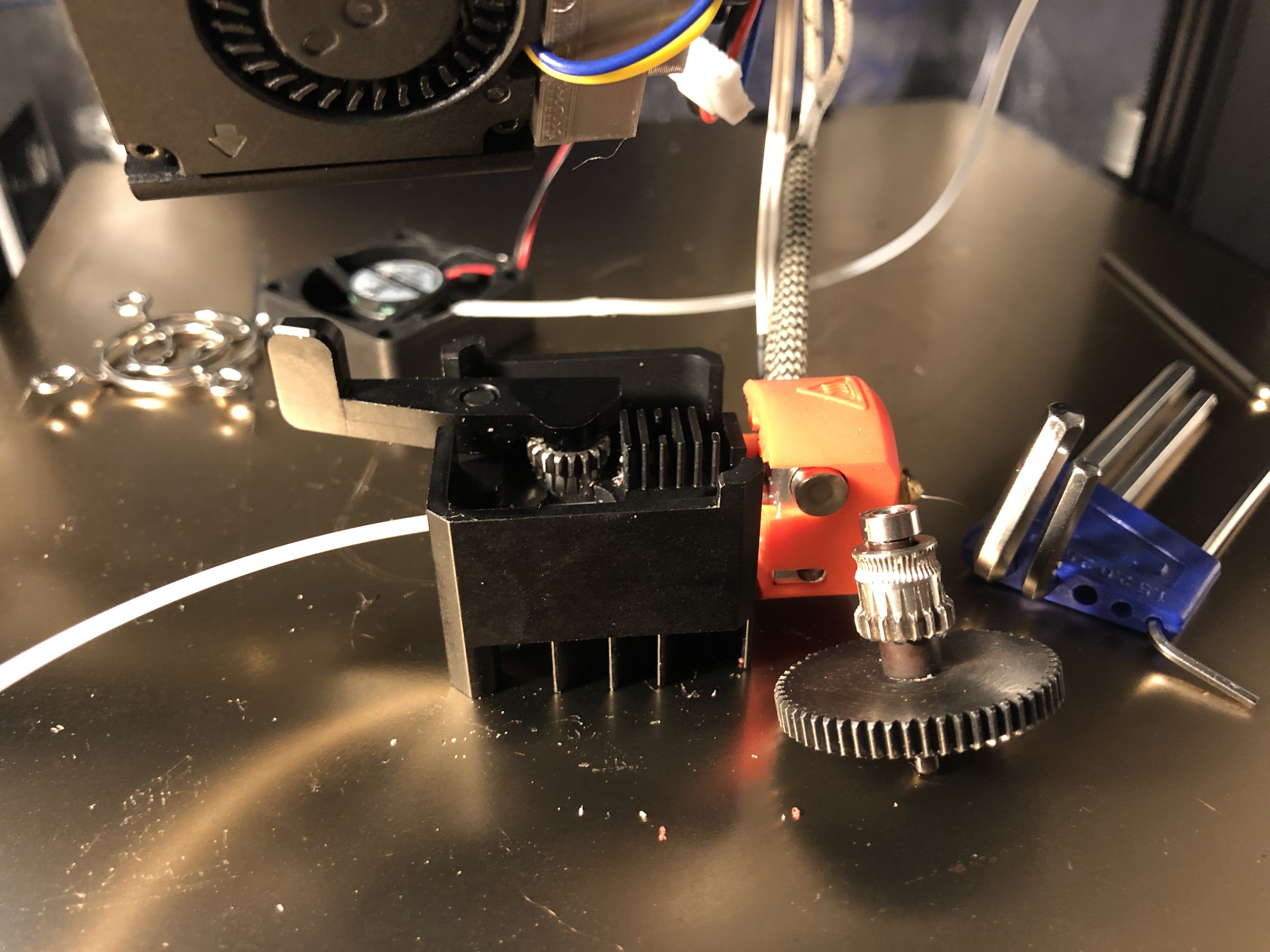 The extruder part with the second step-down gear next to it.
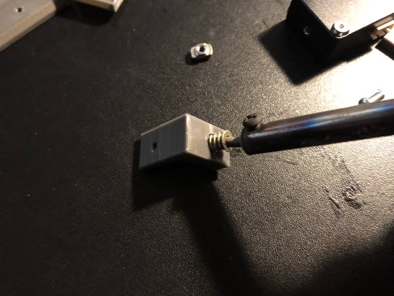
To assemble everything back together, you will find that the tension of the extruder makes it a bit harder to assemble everything together. To help with this I stick a tiny allen key between the extruder arm and the metal. Then you can press the parts together.
Preparing for the first test print
Firmware modifications
Because we lose some build volume in the Y-direction, we need to do some firmware modifications. Firmware modification are not very difficult! You can check this guide I published earlier on how to compile it.
UPDATE 2021-01-31: I’ve added some example configuration files to the CR-6 Community Firmware repository
Follow the guide to do an initial compilation. Then change the things in the Configuration[_adv].h files as detailed below:
Default steps/mm
The extruder uses a 7:1 gear ratio. Although an extruder step calibration is always recommended, we can set an initial good default.
Change in Configuration.h:
#define DEFAULT_AXIS_STEPS_PER_UNIT { 80, 80, 400, 93 }
To:
#define DEFAULT_AXIS_STEPS_PER_UNIT { 80, 80, 400, 932 }
Change the bed size
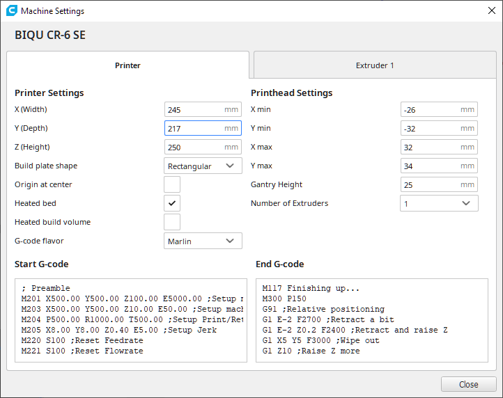
We lose a bit of space in the Y direction, but we can compensate a bit by stretching the size in the X-direction.
Change in Configuration.h:
#define X_BED_SIZE 235
#define Y_BED_SIZE 235

#define X_MIN_POS -5
#define Y_MIN_POS -2
To:
#define LOST_PRINT_SIZE 17 // We lose this in the Y direction

#define X_BED_SIZE 240
#define Y_BED_SIZE (235 - LOST_PRINT_SIZE)

#define X_MIN_POS 0
#define Y_MIN_POS (-1 * LOST_PRINT_SIZE)
Other advanced settings
These settings must be changed in Configuration_adv.h:
Change:
#define RETRACT_LENGTH 6.5
To:
#define RETRACT_LENGTH 0.5
And change:
#define PAUSE_PARK_RETRACT_LENGTH            5
#define FILAMENT_CHANGE_UNLOAD_FEEDRATE     50
#define FILAMENT_CHANGE_UNLOAD_LENGTH      100
#define FILAMENT_CHANGE_FAST_LOAD_FEEDRATE   15
To:
#define PAUSE_PARK_RETRACT_LENGTH            5
#define FILAMENT_CHANGE_UNLOAD_FEEDRATE     20
#define FILAMENT_CHANGE_UNLOAD_LENGTH      50
#define FILAMENT_CHANGE_FAST_LOAD_FEEDRATE   10
That’s it. Compile and flash the firmware.
Slicer settings changes
Change the slicer settings: use a different bed size.
I also have several Cura 4.8 slicer profiles that have worked very well for me:
Essentially you need to turn down your retractions to 0.5mm or even less. More retraction is not necessary.
First boot
The first time you boot the printer, verify that the firmware is flashed and then reset the printer to factory settings.
Double check that all the connections are seated properly.
Testing homing
First let’s double check how much force the strain gauge needs to level. Raise the Z-axis manually until it is pretty much at 2/3 of the total Z-height.
Block the optical sensor on the gantry with some tape. Execute the homing sequence and when the printer finally moves the Z-axis down, block the nozzle as if it was touching the bed and take note on how much force the printer used. You want the mount to flex minimally. If necessary, adjust the strain gauge like in the Strain gauge calibration chapter.
Leveling
You’ve reset to factory settings, so you can now level the bed.
E-step calibration
Do an e-step calibration. This will make sure the extruder steps are set correctly.
Linear advance calibration (optional)
If you have set linear advance, you must recalibrate it. If you forget this, the corners of the first test print (calibration cube) will be overly rounded and underextruded.
Calibration cube
Using the new slicer configuration, slice a calibration cube.
I forgot to set the linear advance down, so all the corners are rounded far too much. But it works!
While the print runs, make sure that the hotend heater connector is properly connected and does not heat up. Heating up is an indication of improper contact.
Quick maintenance check
After a few prints you want to do a quick maintenance check:
- Check all the bolts and nuts.
- Check the cabling and ensure all the connectors are properly seated.
- Make sure there isn’t too much flex in the plastic parts
Final thoughts
This has been a hell of a 1½ weeks figuring this thing out. But it was very fun to do, and I have already completed many TPU prints at decent speeds. This was very much worth it! 😀
Now I have this thing mounted, lets review it…!
If you’d like to support or donate to the CR-6 community firmware development - please check the Credits section of the readme.
What are your thoughts?