How-to: RGB on your printer! Mounting a Neopixel to the Creality CR-6 SE
In this article I will show you how to mount an Adafruit Neopixel to your Creality CR-6 SE. A Neopixel allows for printer-firmware controlled light. You can control a Neopixel from gcode, or let the firmware automatically control it (for instance, when heating).
Gimmick?
I had neopixels on my BIQU B1 printer and thought it was a gimmick, at first. However, Marlin can use the neopixels itself also to communicate the current state.
 When heating the hot-end, Marlin shows the progress as an increasingly amount of LEDs being lit, changing color
You can also fully control it, using the M150 - Set RGB(W) Color gcode.
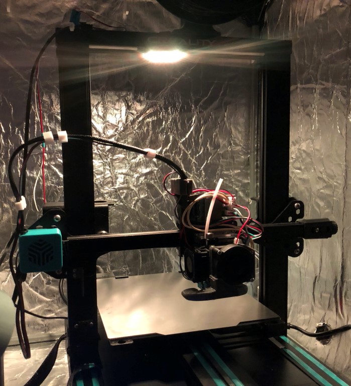
 Mounted on my Kickstarter Creality CR-6 SE
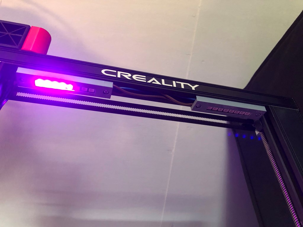
 Mounted on my second CR-6 SE
Bill of materials
For installing RGB neopixels you need at least:
- Compatible motherboard. The BTT SKR CR6 has a dedicated neopixel port. Supposedly the stock Creality board can do it as well, but I’ve not tested it and the specifications are not public.
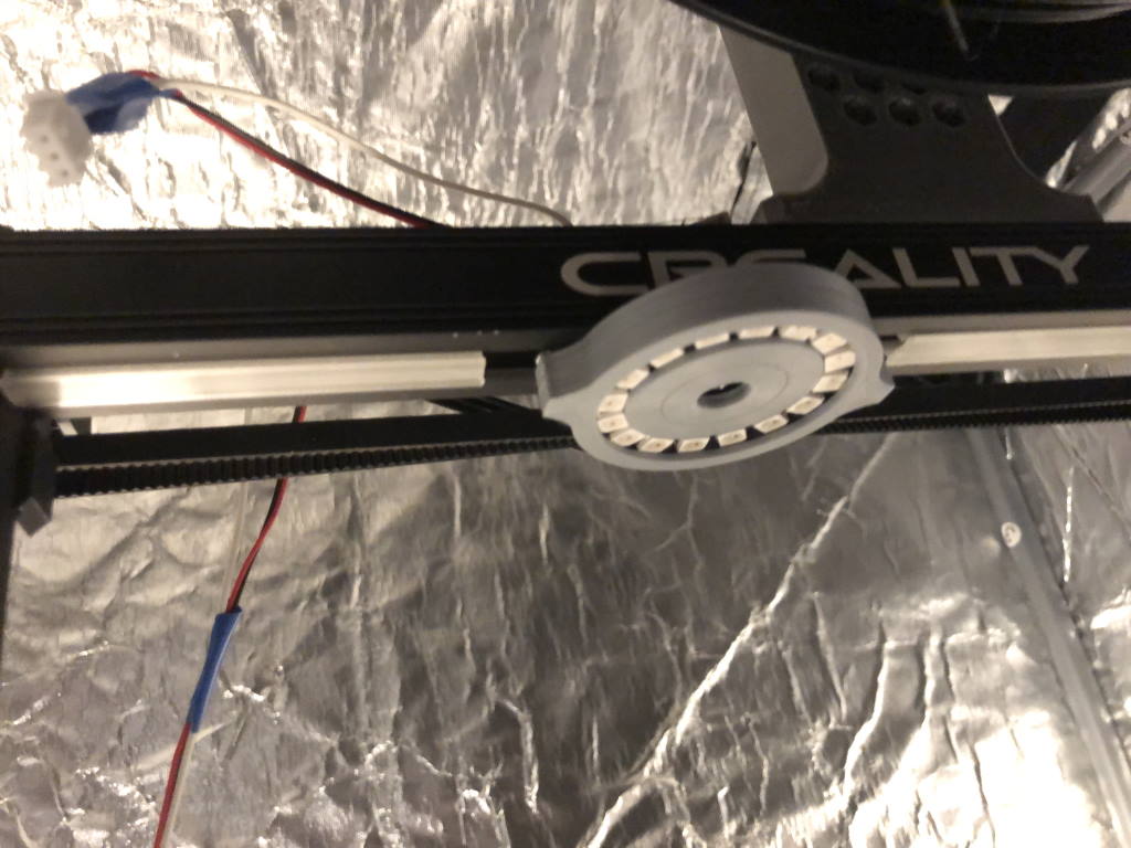
- A Neopixel mount, download from your favorite website or design it yourself. I’ve made two mounts:
- A Neopixel strip or ws2812b Neopixel ring.
- Note that officially the BTT SKR board supports up to 12 LEDs per neopixel according to the manual, but I have 16 pixels on both printers. You may overload the voltage regulator on your board, so be careful and be aware of the risks.
- I used this 16-pixel ring and two of these 8-pixel strips.
- A 3-wire cable
- I used this 15cm JST-SM cable with this 1 meter JST-SM cable. Note that the motherboard has JST-XH connectors, which is a different connector - I just purchased this cable for the wires.
If you don’t have soldering equipment, you need some soldering equipment as well, like:
- A soldering iron
- Soldering flux
- Lead-containing soldering tin
If you don’t have crimping tools, you need that as well. I used:
- This Paron crimping tool from Banggood
- This JST-XH connector set from Amazon
- This JOKARI wire strippers
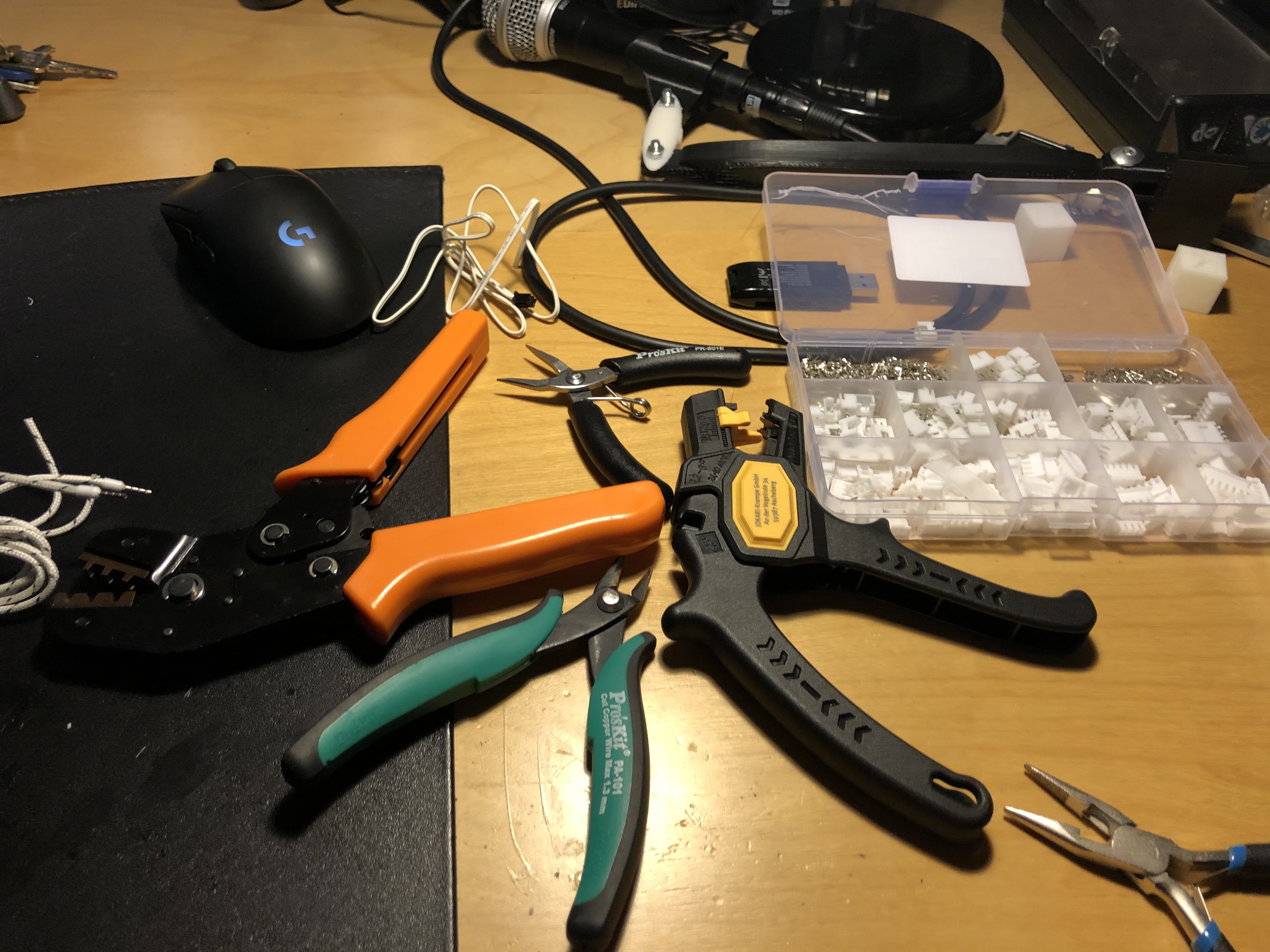 Just a handful of tools you are going to buy some time during your 3D printing life anyway
We will be doing firmware changes as well, so make sure you’ve set-up your development environment.
Mounting
The mounting consists of three major steps:
- Solder cabling onto the neopixel
- Routing the cable
- Crimp connectors onto the cable.
Soldering
Soldering the neopixel assembly is the most difficult and tedious process, because the soldering pads
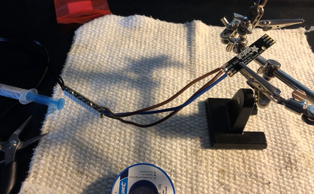 A helping hand (the thing with the crocodile clips) comes in very handy
I’m not going to explain soldering here, there are much better sources for that on the interwebz. You need to solder to the 5V, data IN and GND pads of your neopixel. No
Most important to check after soldering:
- Is the soldering connection solid?
- Measure with a multimeter that the 5V, GND and data line is not shorted and is properly connected.
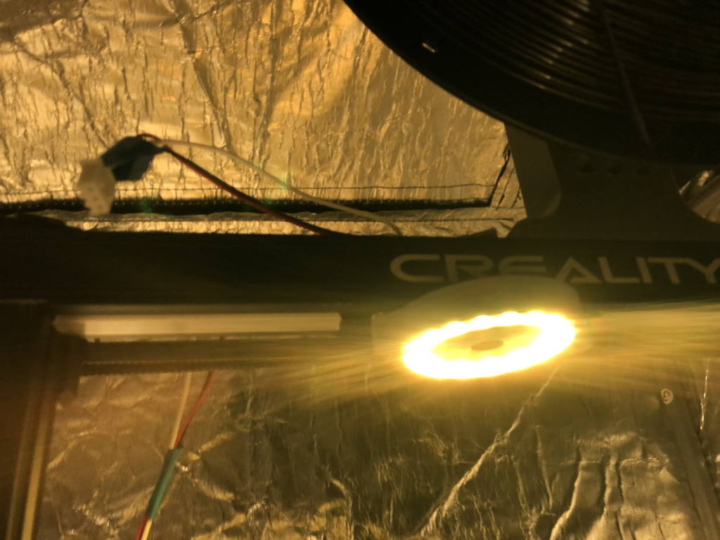
Routing the cable
The first step is routing the cable. There are a few holes on the CR-6 printer that allow cables to go the motherboard. For my purposes, I found routing easiest through the hole where the flatcable also goes.
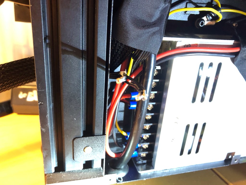 Routing it through the hole, it routers along the power supply cables through the motherboard
Also take this chance to check if all the wiring is still proper.
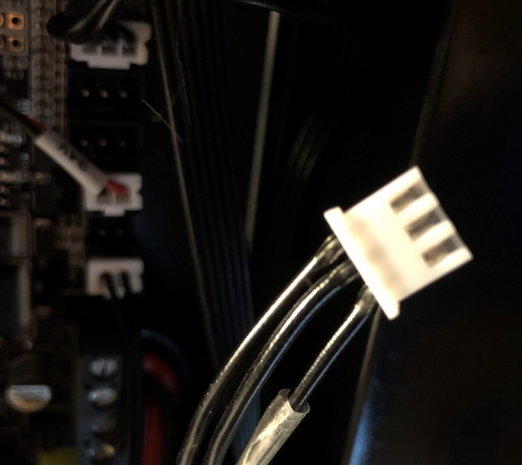
Crimping the cables
Finally, you need to crimp a JST-XH connector onto the neopixel cable. Take note of the pin-out for your particular motherboard. BigTreeTech publishes the pin-out of their board online. As far as I know Creality does not have public pin-outs for their board.
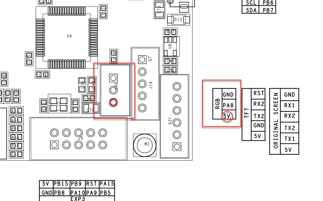 You need the RGB connector. Note that the 5V line must match with the 5V line of the neopixel, data line with the “data in” port.
If you have the wiring wrong, your board will most likely survive. It did in my cases: my board simply went into protection and did not boot Marlin. Still, double check your wiring.
 Crimping is not the most fun to do, but everything is very neat and tidy afterwards. It is rewarding 😉
Firmware changes
You also need to make some firmware changes. You can check the guide I published earlier on how to compile firmware.
There is only one file you must change: Configuration.h.
Find the section that says:
// Support for Adafruit NeoPixel LED driver
//#define NEOPIXEL_LED
#if ENABLED(NEOPIXEL_LED)
  #define NEOPIXEL_TYPE   NEO_GRBW // NEO_GRBW / NEO_GRB - four/three channel driver type (defined in Adafruit_NeoPixel.h)
//#define NEOPIXEL_PIN     4       // LED driving pin
  //#define NEOPIXEL2_TYPE NEOPIXEL_TYPE
  //#define NEOPIXEL2_PIN    5
  #define NEOPIXEL_PIXELS 30       // Number of LEDs in the strip. (Longest strip when NEOPIXEL2_SEPARATE is disabled.)
  #define NEOPIXEL_IS_SEQUENTIAL   // Sequential display for temperature change - LED by LED. Disable to change all LEDs at once.
  #define NEOPIXEL_BRIGHTNESS 127  // Initial brightness (0-255)
  //#define NEOPIXEL_STARTUP_TEST  // Cycle through colors at startup

  // Support for second Adafruit NeoPixel LED driver controlled with M150 S1 ...
  //#define NEOPIXEL2_SEPARATE
  #if ENABLED(NEOPIXEL2_SEPARATE)
    #define NEOPIXEL2_PIXELS      15  // Number of LEDs in the second strip
    #define NEOPIXEL2_BRIGHTNESS 127  // Initial brightness (0-255)
    #define NEOPIXEL2_STARTUP_TEST    // Cycle through colors at startup
  #else
    //#define NEOPIXEL2_INSERIES      // Default behavior is NeoPixel 2 in parallel
  #endif

  // Use a single NeoPixel LED for static (background) lighting
  //#define NEOPIXEL_BKGD_LED_INDEX  0               // Index of the LED to use
  //#define NEOPIXEL_BKGD_COLOR { 255, 255, 255, 0 } // R, G, B, W
#endif
Follow the following steps:
- Uncomment
#define NEOPIXEL_LED - Set
NEOPIXEL_TYPEtoNEO_GRB, at least for the two neopixels I linked above. - Set
NEOPIXEL_PIXELSto the total number of neopixel LEDs that are connected. 16 in my case. - Uncomment
NEOPIXEL_STARTUP_TEST, then Marlin will let the pixels change colors as Marlin starts up.
Compile and flash your firmware.
Summary
That’s it! You’ve now successfully installed neopixels on your printer.
 Mounted on my Kickstarter CR-6 SE
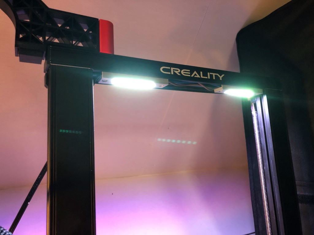
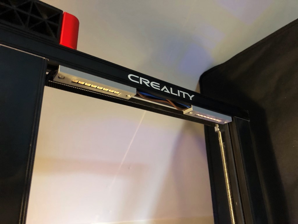 Mounted on my second Creality CR-6 SE
Once this feature request has been implemented in the CR-6 Community Firmware, Neopixels will also be controllable from the touch screen. When you have a BTT TFT, you are already able to control the neopixels from that screen.
What are your thoughts?