How to: Flash Marlin on Anet ET series printers
After my BIQU B1 review and work on the Creality CR-6 community firmware I got contacted by the 3D printer manufacturer Anet 3D to test and review their Anet ET4 Pro 3D printer. The Anet ET series run on Anet’s propietary firmware, but it is actually possible to flash them to the well-known printer firmware Marlin! However, it is a little bit more involved than just putting a bin file on the SD card. This article will show you how to flash Marlin to your Anet ET printer.
Requirements
There are several things you need for this guide.
Anet printer
First of all, ensure you have an Anet ET series printer. I used this procedure on an Anet ET4 Pro printer.
Because the Anet ET series printers are very much alike and all use a very similar mainboard, this guide should work on both the ET4 and ET5 series.
ST-Link
We can’t flash the firmware via an SD card, we need to do it the first time directly to the 32-bit ARM processor on the main board. For this we’re going to use an ST-Link.
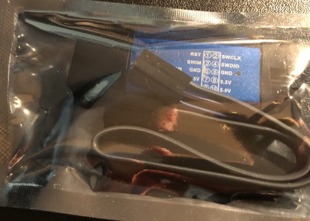
You can get this on your favorite webshop. You can either buy the official ST-Link from ST Microelectronics or a clone like I bought. In my case I bought the AZDelivery ST-Link V2.
Bootloader
It is very useful to have a bootloader, which allows you to update your firmware without needing to open up your printer every time.
For this, I’m assuming you use the openlbt bootloader for Anet ET printers. Download the openblt_et4.bin file.
Firmware
You will need a build of Marlin 3D printing firmware. You can use the following options:
- Official “Open source” firmware by Anet - you can get this from their download page under the “Open source” button. These builds are precompiled.
- Community firmware by David on Github and compile it yourself
In my case I did some modifications to improve the quality of the printing, so I forked Davids project to my own ANET-ET4Pro-Marlin repository. With the right changes in Marlin/EasyConfig.h it should still be compilable for other Anet ET printers.
Ensure you’ve compiled the firmware for offset 0x08100000 because we need some space for a bootloader. When your firmware is compiled succesfully, a firmware.srec file will be generated in the .pio\build\ET4 folder. Put that file on a micro SD card.
ST-Link software
For the ST-Link, even if you have a clone, you need the official ST-Link driver available from the ST website and the ST-Link in-circuit debugger/programmer software. Install both pieces of software.
Preparing the printer
First you need to have the printer in a position so you can see the display, access the power controls, and access the mainboard. Unload any filament you have and gently place it so you can access everything.
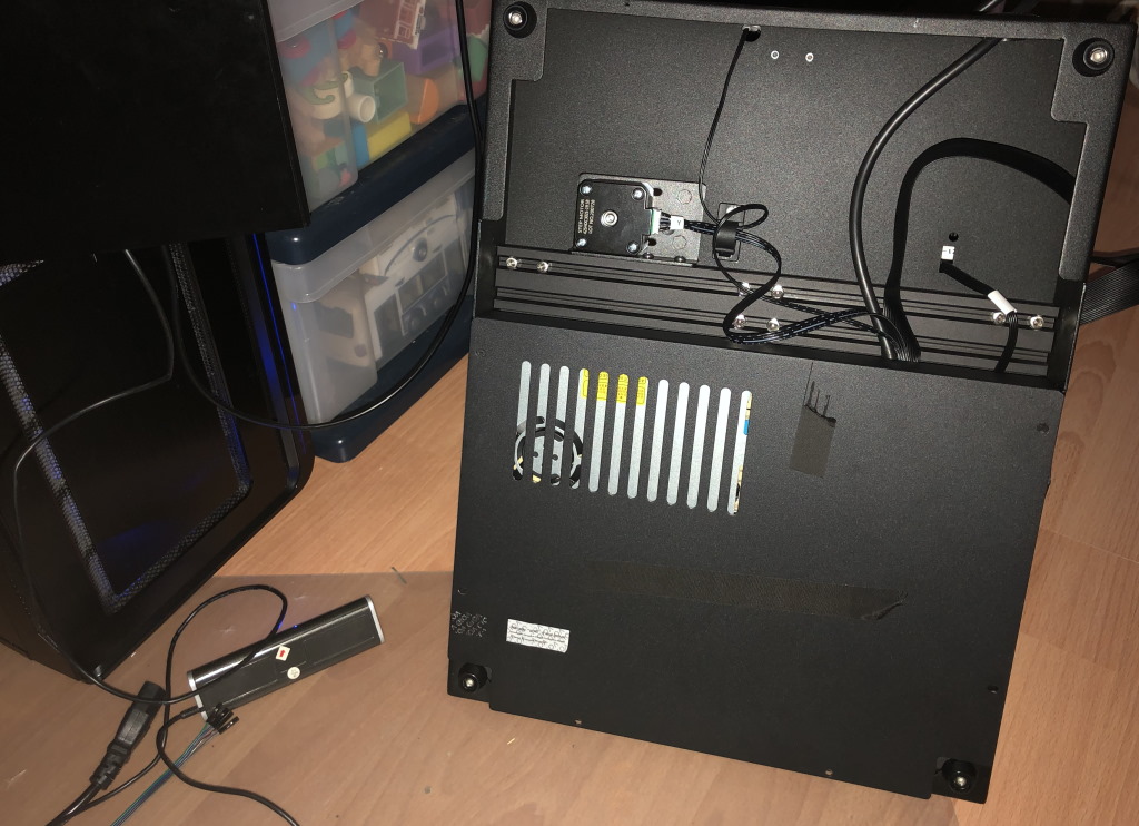
I positioned it actually wrong here, I later found out I couldn’t see the screen
Note: officially this will void your warranty, but in another statement Anet states they can only help you when you run the official firmware, so I’m not sure what their current opinion is of this.
Unplug the printer from the live electricity, and remove the motherboard cover. The motherboard cover has a little cable branch attached to it, gently remove this.
ST-Link wire up
Now it is time to wire up the ST-link. My ST-link is for both 8-bit and 32-bit processors, but since the Anet ET runs a 32-bit STM32F407VGT6 microprocessor, we’re going to use the 32-bit protocol for talking to the processor.
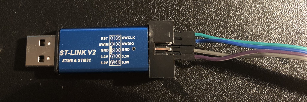
At the ST-Link adapter side you’re going to wire up the following pins:
- SWCLK - green - the SWD clock signal
- SWDIO - blue - the SWD data signal
- GND - gray - the common ground signal
- VCC - purple - you won’t wire this up at the motherboard side, but because my other pins were almost falling out of my ST-Link, this kept a bit of friction on the pins
Note that in this picture these are the bottom-most pins. The color of your wires of course don’t matter, as long as you wire the pins at this side correctly to the printer motherboard side.
Printer motherboard wire-up
At the motherboard side, there will be a small pin header near the STM32 ARM processor.
- There will be a pin labeled with the letter “G”, this is the ground pin (GND). In my case I wired my gray wire to it.
- The pin next to it is the clock signal (SWCLK), in my case the green wire.
- The pin next to the clock signal pin is the data pin (SWDIO), in my case the blue wire.
- The last pin header will not be wired and must be left disconnected.
Don’t worry if you interchange the SWCLK and SWDIO, it won’t cause any harm to your board. You will just not be able to connect to your printer. The most important thing is that you have the GND pin right, and the VCC disconnected.
Boot up
You can now plug in the power cord and turn on your printer. Note: the contacts that go to your 230V/110V live electricity are exposed at the power supply. Do not touch them.
Verify that the printer boots to the start screen.
ST-Link software flashing instructions
Connect the ST-link to your computer and start the ST-link software. With this software you are able to talk to the STM32 ARM processor directly.
Backup
First, let’s backup the current firmware. This is especially important for the Anet ET4 Pro printer, because there was never a firmware download for it. Still, do this step anyway if you have a different printer.
Connect to the ST-Link using the context menu, and choose “connect”.
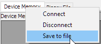
After choosing connect and being succesfully connected, you can choose “save as file” to backup the existing flash contents. A file browser will open and you can save your firmware (like ANet-ET-firmware-backup.bin).
Flashing
We’re not going to flash our precompiled firmware directly, but use a bootloader instead. We flash the bootloader once, and after that we can just use an SD card to do any further firmware updates.
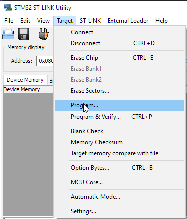
Go to Target -> Program, then choose the openblt_et4.bin file and ensure the correct offset as shown below (0x0800000) and other options like below are selected.
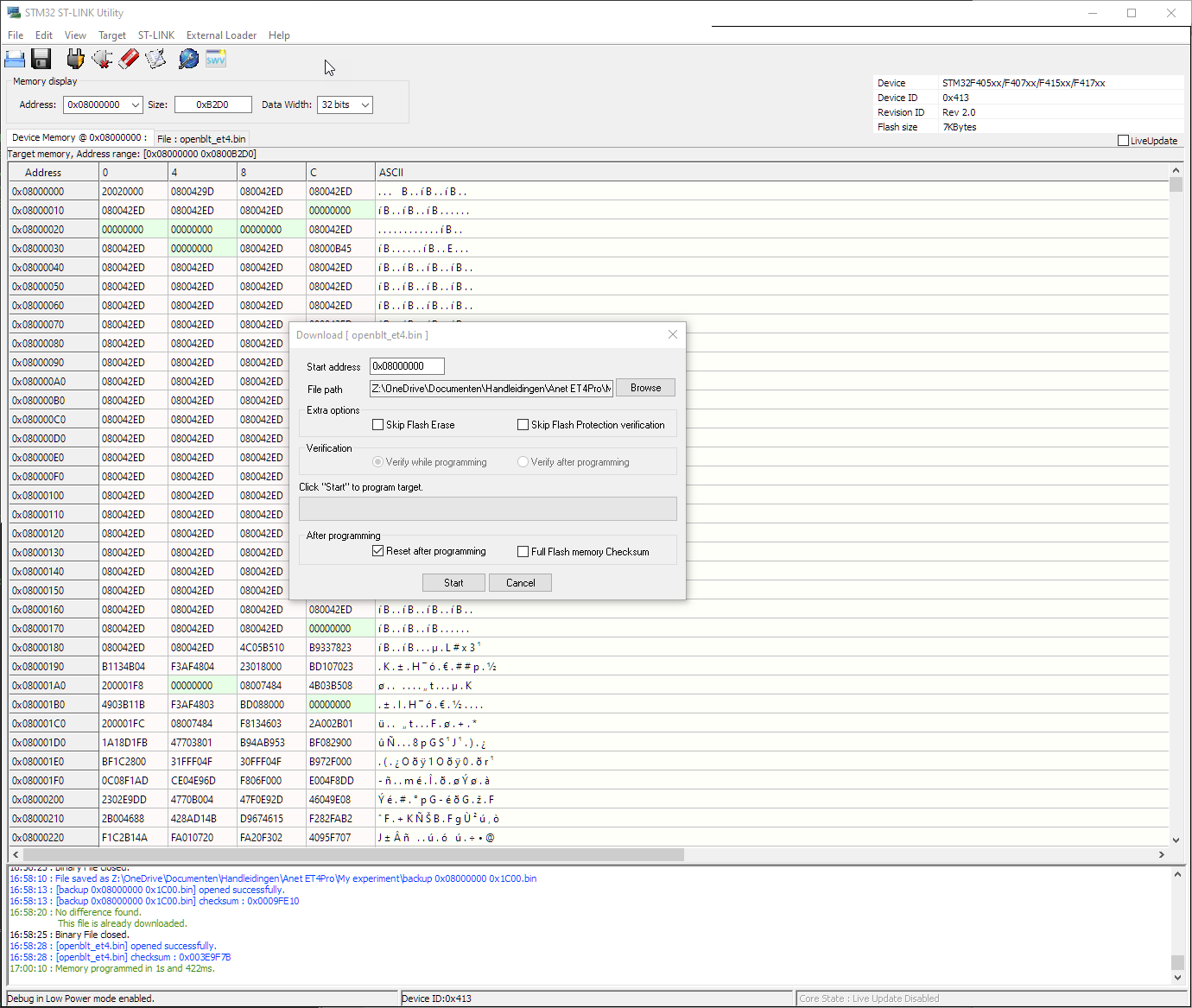
Start the flashing process by clicking “Start”. It will take a few moments. If it fails, you can retry it without issue.
Booting
That’s it for the flashing process. Turn off the printer, disconnect the power, and remove the ST-Link from the printer.
Now, take the micro SD card you’ve put the firmware.srec file on, and stick it in the printer. Connect the power, and turn on the printer again.
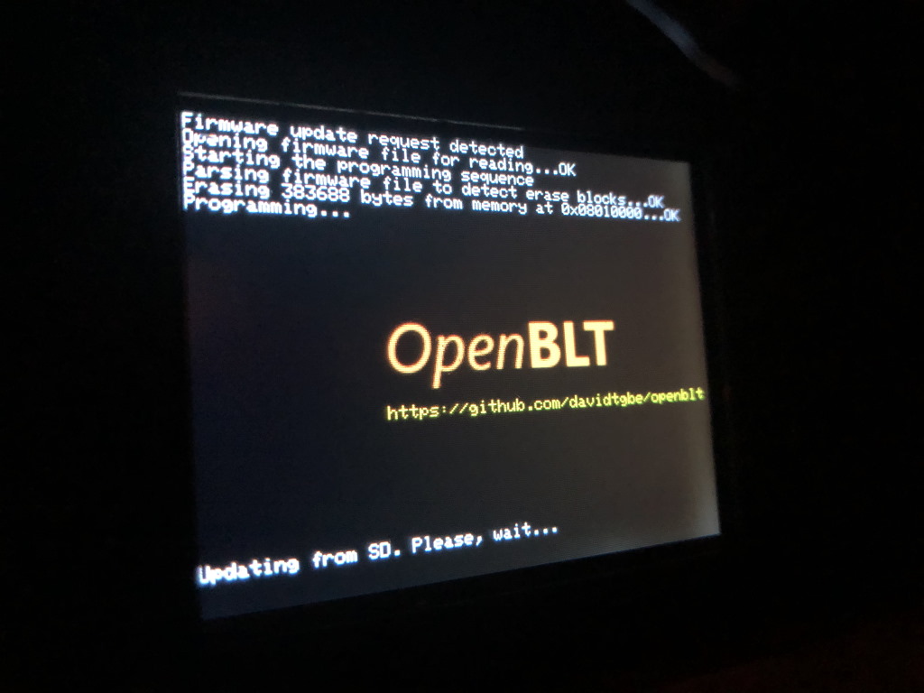
If you’ve done everything right, OpenBLT will find the firmware file and start flashing the file to the ARM processor. This takes a few moments, and after it’s done…
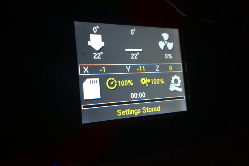
… Marlin will boot to the status screen. Hello world!
Final touches
There are still some things left to do before you can fully enjoy your printer. First, tidy everything up, close the motherboard cover and put your printer where it belongs.
Touch screen calibration
Most likely your touch screen will not detect touches correctly, so you need to calibrate it first.
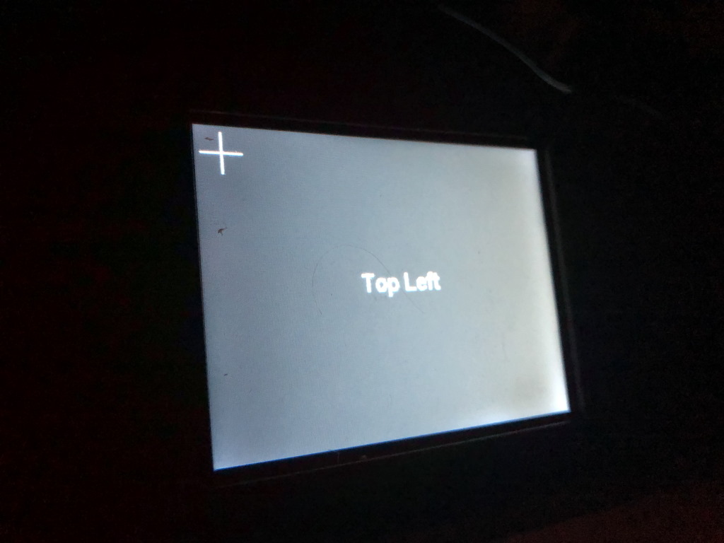
For this, press and hold the touch screen for 5 seconds until the calibration screen appears. Using a stylus, or Allen key touch the screen in the corners as directed. When done, you will automatically return to the status screen.
I’ve found that the touch screen is actually too small for Marlins rich (and sometimes clunky) menu structure, so you need to use a pointing device like a stylus from now on.
Calibration
Before you do any prints, you will want to do the basic calibration steps from the Teaching Tech 3D Printer calibration site:
- Do PID Autotune to learn Marlin to control the hot-end and bed
- Relevel your bed - for auto bed leveling the option from the menu is missing, you need to issue G29 from Octoprint or Pronterface.
- E-step calibration to extrude the correct amount of filament
Conclusion
I hope this has helped you flash a firmware to your Anet ET 3d printer. Good luck further tuning of Marlin!
What are your thoughts?