BIQU B1: Unboxing and assembly
Finally I received the BIQU B1 from BIGTREETECH. It was stuck in Dutch customs for almost a month - also partially blaming Fedex for this. But, it is finally here! Let’s unbox and assemble this printer!
BIQU?
BIQU is not yet very known in the 3D printing market… when it comes to fabricating printers. But the parent company, BIGTREETECH, must sound some bells with any 3D printing geek. For those who don’t know it: They are well-known for their 3D printer upgrades, like motherboards (the “brains” of the operation) and (touch) screen upgrades for the printer.
With the BIQU B1, BIGTREETECH wants to make an entrance in the 3D printing market. This is a very potent, growing, market. Printers are being produced for lower and lower prices - and at the same time the quality of these machines increases dramatically. Another manufacturer of less expensive 3D printers is Creality, which has gotten a big foothold of the market with their Ender 3. I had a very bad first impression of them though.
With this being said, let’s get to unboxing!
Packaging
3D printers are sensitive devices and work on very tight tolerances. Because of this, it is important that a printer is packaged well. BIQU has understood this.
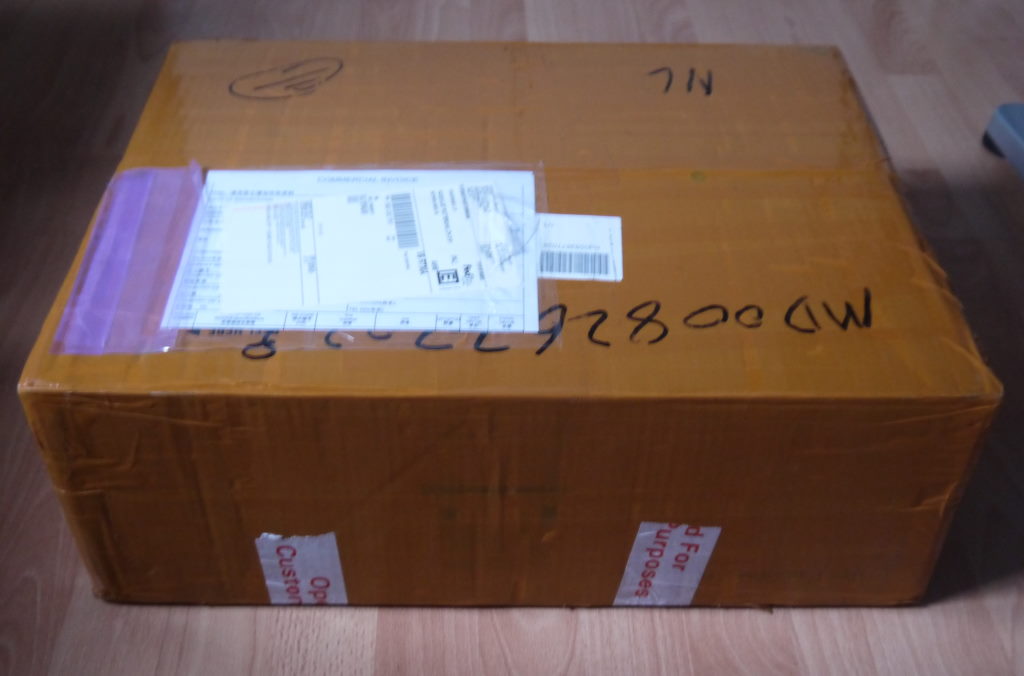
The BIQU B1 comes in a firm box, wrapped in packaging tape. Although it might not have been intended for resilience against water or moisture, I do think it doesn’t hurt. From what I’ve seen from delivies from some other printers so far, when a printer is in a sea container, it may get exposed to water even! Still, a lot of tape did make it a bit harder to unpack. Nothing a Stanley blade can’t handle though.
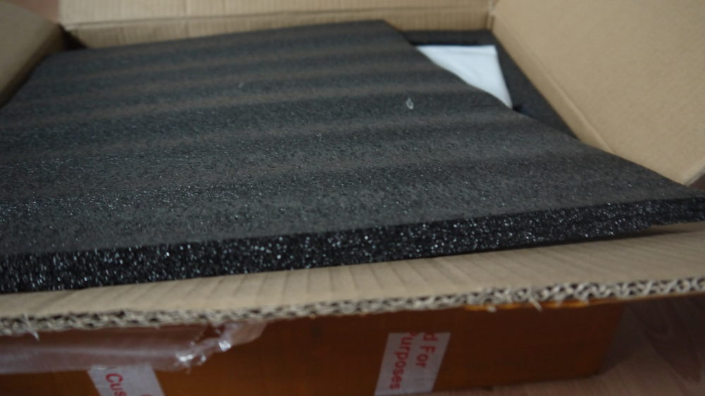 Take a moment to appreciate the thick foam that is used as the first layer of the packaging. It keeps the printer safe while being handled rough by the delivery service.
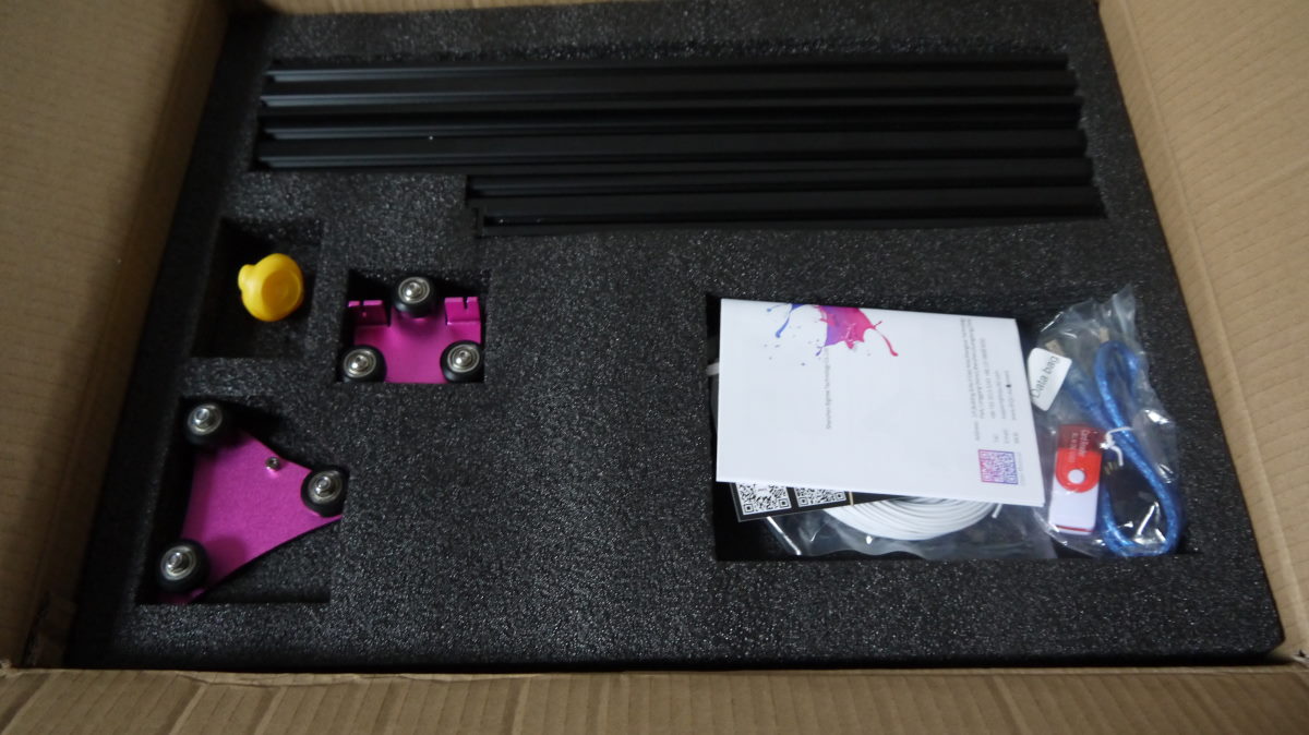
With the top layer of foam removed you can see right off the bat that this printer requires some assembly. This is a good thing. If you put a printer together yourself you are in control and you’ve touched every part. With all the vibrations during shipping, you can’t assume a pre-assembled printer will be alright - so you need to check every nut and bolt anyway. Printers need to work with very small tolerances - so any loose bolt can potentially ruin your print. I am not very mechanically inclined - I might call myself a klutz even - but I did manage to assembly this printer. I think that anyone can put this 3D printer together - and you learn a lot while you do assembly it.
The first layer contains some parts you need for later in the assembly process and the main parts that will form the gantry.
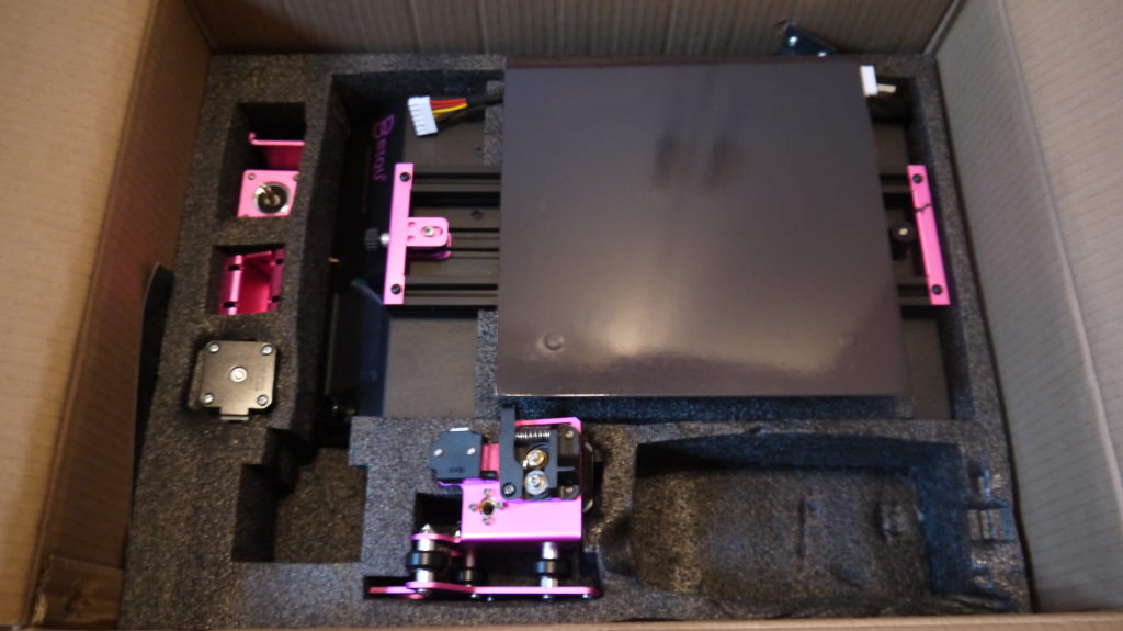
The second layer contains the most exciting parts: the printer base itself, stepper motors, and feeder. Carefully lift the parts, and finally the base out of the box.
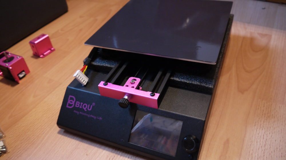 The base is already pre-assembled, but we will tighten the necessary bolts later in this guide.
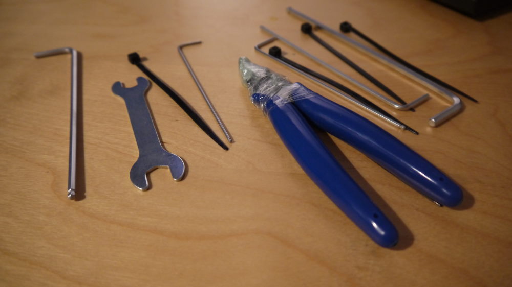 As you can see, this printer comes with a some tools - so have them ready. Note the Allen keys have a ball head at the end. This helps adjusting nuts which you can get to at a 90-degrees angle.
Nuts and bolts
There are about 20 steps to follow in the instruction manual. There are a lot of bolts, nuts and screws to use - but BIQU includes all the tools you need. Every part you need is in a separate plastic bag with a label on it referring the relevant step.
A lot of bag and bolts - it looks a bit daunting at first - but you’re guided step-by-step!
Base disassembly and electrical work
Before we go into assembly I like to do a little disassembly first. This can give a good judgement about the quality of the rest of the printer. If there are issues with electrical wiring - it doesn’t give much hope on the rest of the printer. But, as it stands BIQU does a good job at the wiring.
For starters, look at the electrical switch and how it is wired.
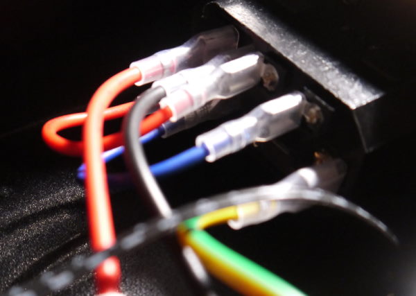
What manufacturers often forget is to wire both neutral and live through the switch. Why is this important? Because in European countries like the Netherlands there is no guarantee which wire is live or neutral. If you only switch one off, then the device is still on power. BIQU switches both wires, and also uses a fuse to protect the wiring of the printer. If you take Creality for instance, they do it wrong and only wire live.
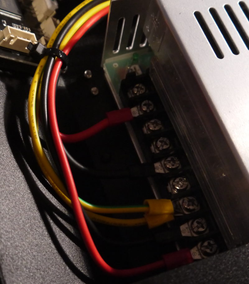
The wiring to the power supply is also very neat. Note that there are two wires used for grounding: one wire goes to the power inlet, the other wire is used for grounding the frame and base of the printer. I’ve used my multimeter to check whether this is actually done right and it shows a very low resistance (a few Ohms at most). Regarding electrical safety, I have no concerns about the BIQU B1.
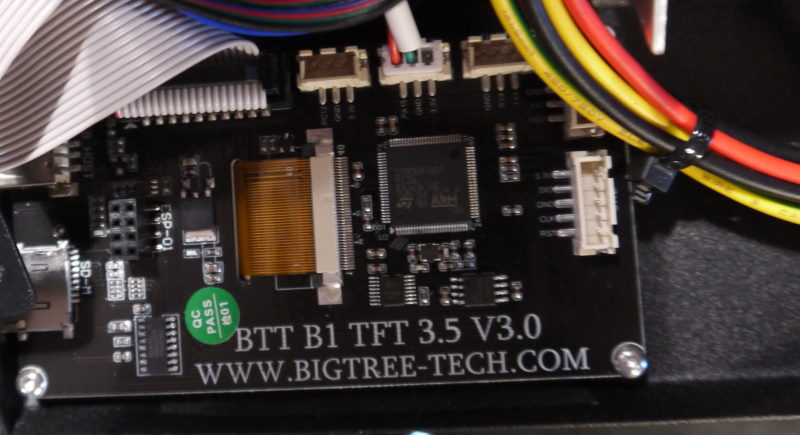 The touch screen of the BIQU B1 is made by BTT - and this touch screen is a popular upgrade for Creality Ender printers
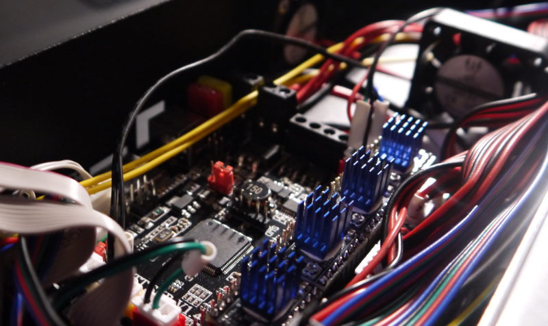
The motherboard of this printer is interesting. This a SKR v1.4 motherboard from BTT with removable stepper drivers. This means that at some point you can choose to swap out your stepper drivers with a newer or better model, or if the stepper driver is defect simply replace it. It is very nice this option is there - so you can use it when you need to.
However, replacing stepper drivers right away is not necessary. The BIQU B1 comes with the Trinamic TMC2208 stepper drivers. These stepper drivers are silent, so you don’t have to worry about any 1980’s “dot matrix” noise while the printer runs.
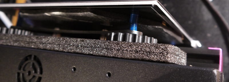 The BIQU B1 features a heated bed. This is optional - but recommended - for PLA printing, but necessary for PETG and ABS printing. The heated bed is insulated at the bottom, so as much heat as possible is distributed on the bed.
You can also see that the printer is manually leveled and has the “extra tight” spring upgrade that is popular on Creality Ender printers. Even the Ender 3 V2 does not come with such upgraded springs. Note: The foam shown here is used for securing the printer in the box - at this point I hadn’t removed it yet.
Assembly
Let’s get onto assembly. The first thing to you is to plug in the bed. Why the bed? Because the connector on the bed has long pins, and you don’t want to bump into them while assembling.
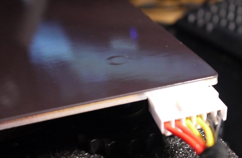 Note that this cable has no strain relief - but I don’t expect it to have much strain at all during daily use - so I find that acceptable.
Gantry part 1
First take the largest aluminium extrusions and screw them to the pink end caps. These two extrusions form the vertical part of the gantry.
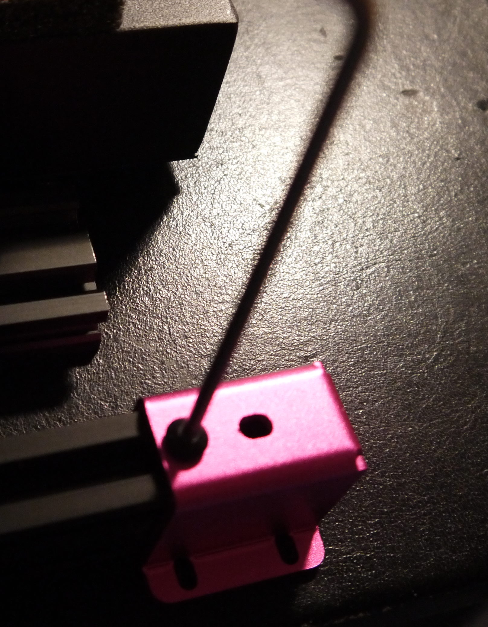 First screw in the bolts at the side but don’t tighten them yet.
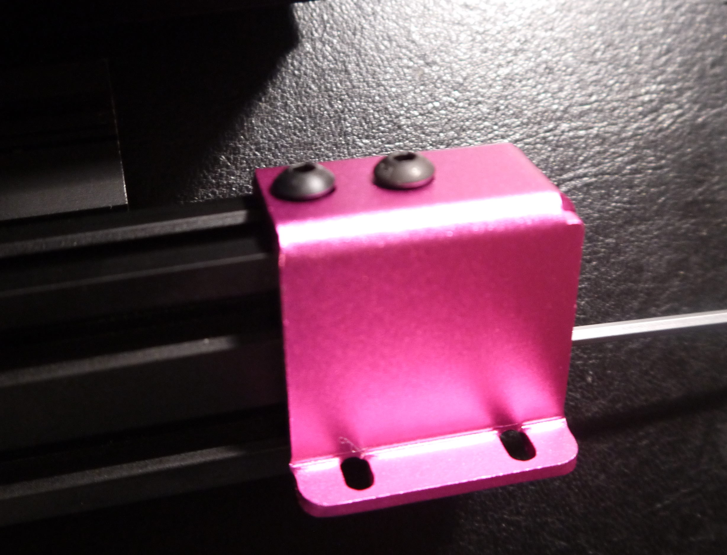 Next, screw in the bolts at the bottom and tighten these. Now tighten the bolts at the side
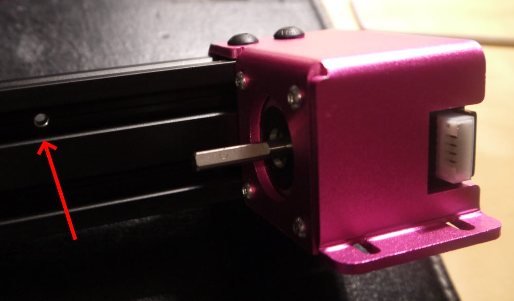 Do the above steps for the extrusion with the stepper motor as well but note that the small hole in the extrusion must be aligned outside. This hole will later be used to fit the Z-endstop.
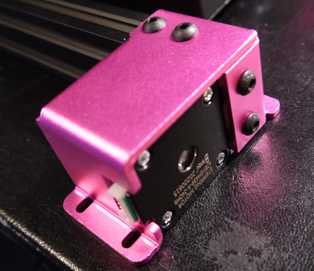 The stepper motor is already mounted to the pink end cap where you mount the aluminium extrusion on.
Bed rollers
Before we continue, let’s first properly tension the bed rollers. The Y-axis of the printer moves on four wheels. Two wheels are fixed, two wheels are mounted with eccentric nuts.
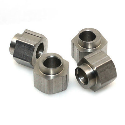 Eccentric nuts are off-center and allow moving the wheels away or to the aluminium extrusion
Now we don’t have the gantry mounted yet, it is a bit easier to reach the bed rollers. Most likely you will need to tension or loosen them. To determine that, try to wobble your bed.
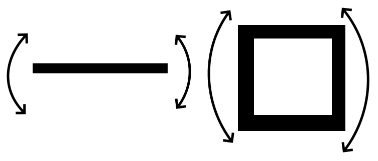 Try to wobble the bed in both lateral and and horizontal direction. If you fell any movement except for movement parallel to the Y-axis, you need to tension the wheels.
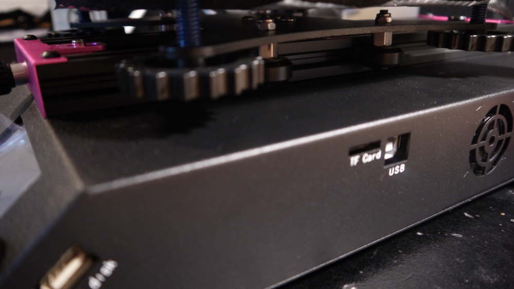 With the wrench you can tension the nuts under the bed.
When tensioning your bed, you need to do this Very Carefully. You turn the eccentric nut a bit, test again and then repeat as necessary. When there is no wobble, check whether you can still move the wheels by hand. If you can’t, you need to loosening the wheel by turn the eccentric nut a tiny bit. You can’t skip this step, because you may wear out your wheels otherwise.
When the bed is sturdy, check if it isn’t binding when you move it back and forth and you’re good to go.
Gantry part 2 - going up!
Mount the aluminium extrusions to the side of the printer. This is easy, because you don’t need to lift the printer up to do this.
Don’t tighten the screws fully yet, it may have a bit of play because the X-axis will be mounted and that will determine how we will tighten these screws
Next, take the connecting piece for the lead screw (in the bag named “Coupling device”). It has very small nuts, called “grub screws”, which you need to screw out a little bit.
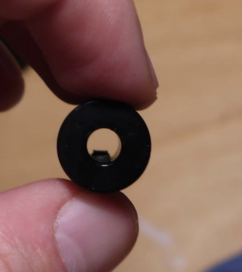 In this case the grub screw was screwed in
The lead screw will be mounted on top of the coupling device. The stepper motor axis has one flat side, and you need to align the grub screw to that.
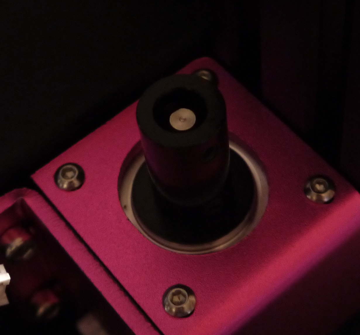 Note the flat side on the stepper motor axis. The coupling device is far too low in this picture though, the lead screw does not have anything to hold onto.
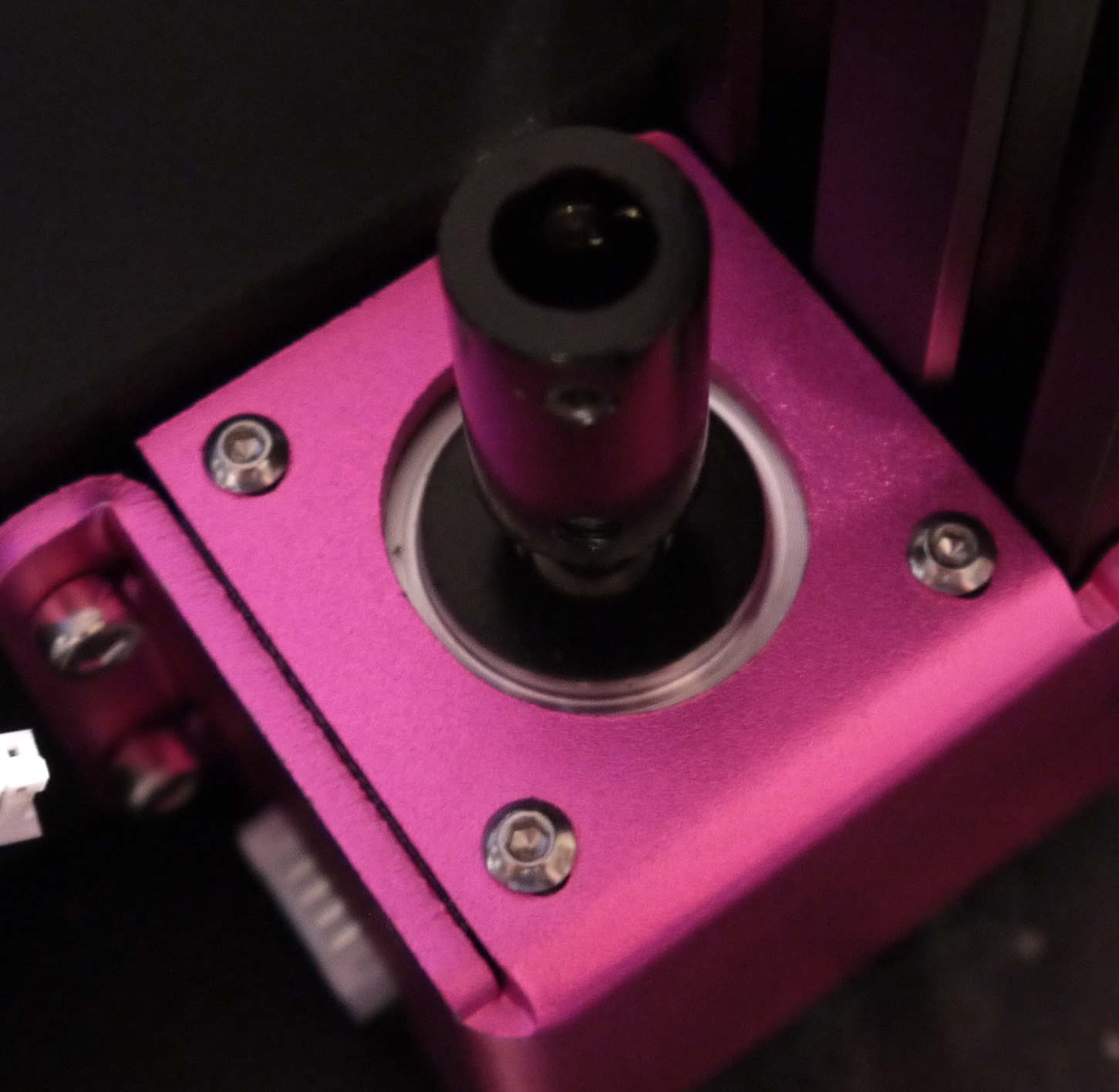 Center the coupling device so that the motor axis is midway of the coupling device, then tighten the grub screw.
Now you can take the lead screw and put it in the coupling device.
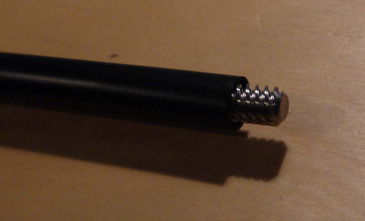 Note how the lead screw is protected by the rubber packaging? Some manufacturers already lubricate the lead screw. For this reason, handle lead screw only with the rubber protection.
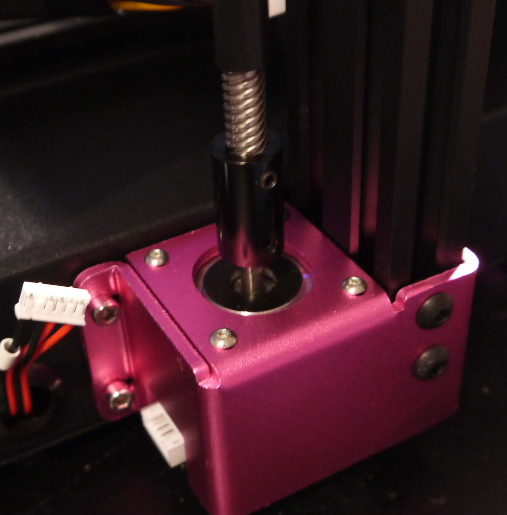 Put the lead screw in the coupling device, then tighten the grub screws. There are two of them.
Gantry part 3 - X-axis
A part of the X-axis assembly has already been pre-assembled. It contains the X-axis stepper motor, the feeder stepper motor, the filament run-out sensor, and the feeder itself.
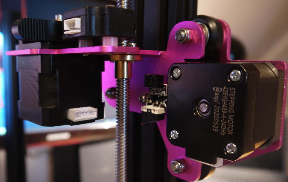 Align the X-axis assembly with the lead screw and the aluminium extrusion - then turn the lead screw manually
Gently lower the X-axis assembly by turning the lead screw using the coupling device
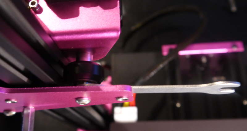 Don’t forget to properly tension the wheel on the X-axis assembly!
There is another part of the X-axis assembly which goes on the other aluminium extrusion. The side with the two fixed wheels goes on the right side of the gantry, the single wheel on the “inside”.
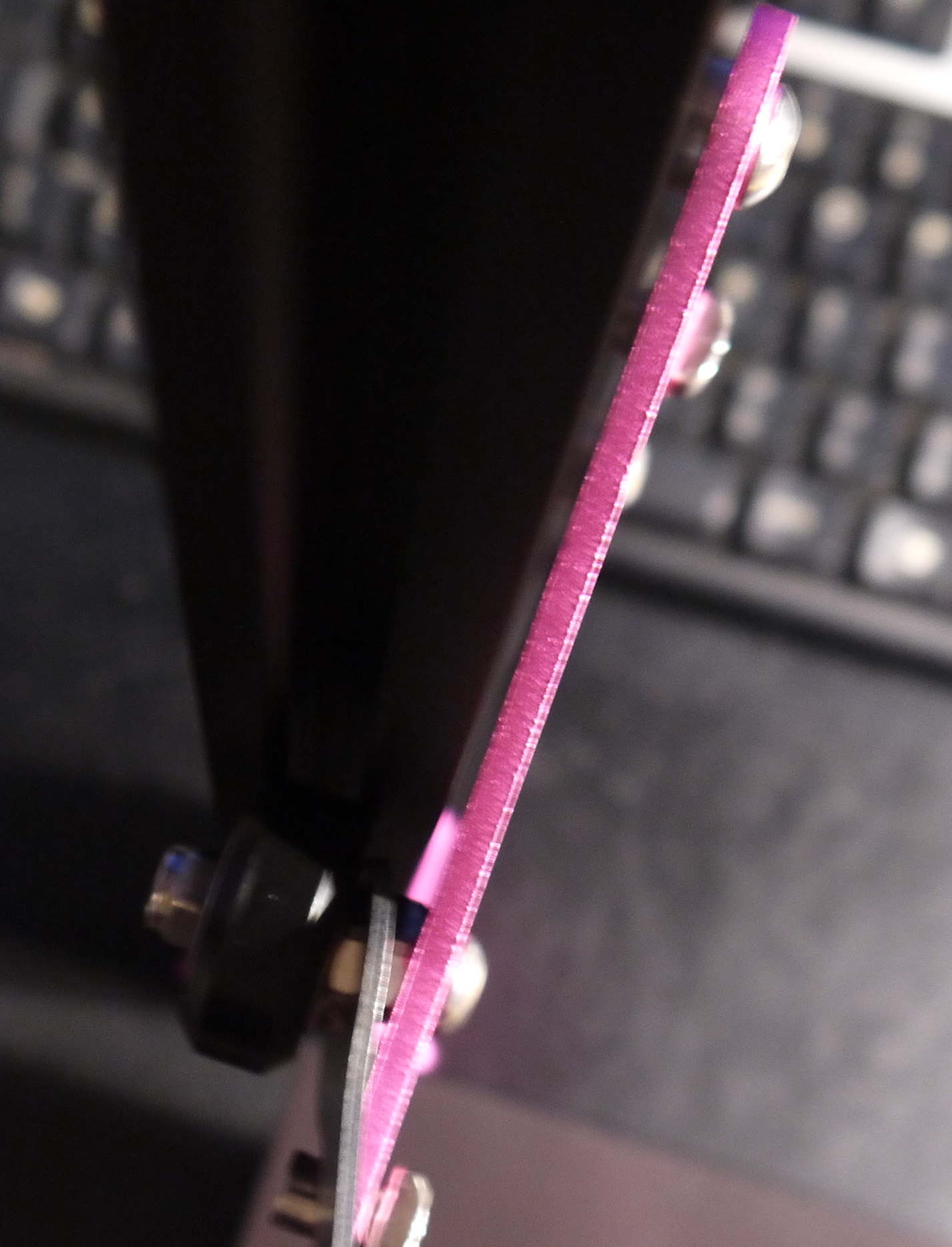 The other part of the X-axis assembly has needs to be tensioned as well
If both items have been mounted, we can mount the top bar.
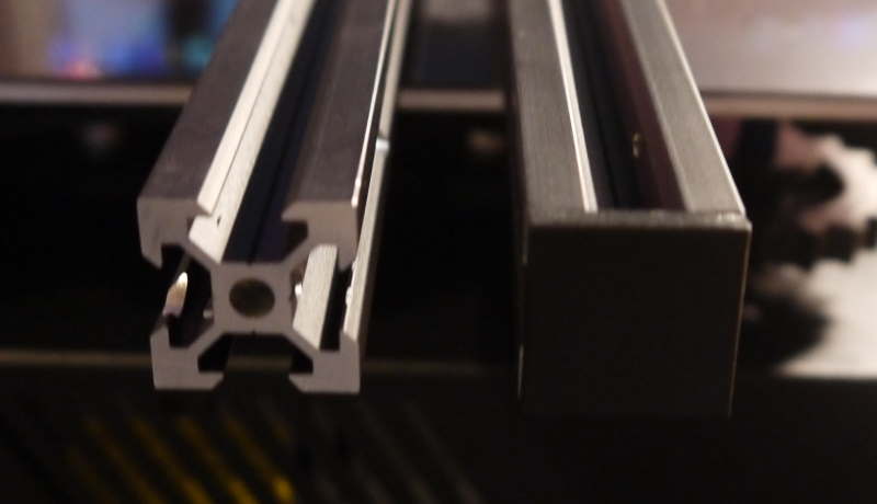 Guess which one?
Mount the top bar, but do not tighten the screws just yet.
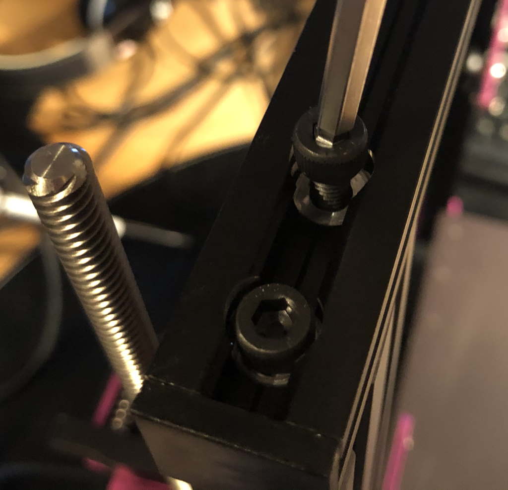 We don’t tighten the screws just yet - we will let the X-axis determine how this needs to sit
Now we are ready to mount the X-axis. Align the extrusion with the right side first and mount it.
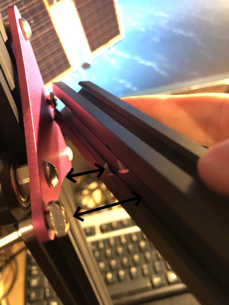 The aluminium extrusion has a small extrusion that matches the nut at the roller side.
The T-nuts are a bit tricky to get right if you’re doing this for the first time. To get them in the aluminium extrusion, first loosen the nut so that the T-nut turns, then tighten it. The T-nut will grab onto the inside of the aluminium extrusion.
The left side of the X-axis, at the feeder, is quite simple. These are just some bolts.
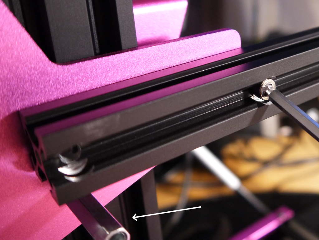 Note that you also need to mount this aluminium nut that will act as the X-axis endstop trigger
Now the X-axis is fully mounted - turn the Z-rod so that the X-axis moves fully to the top. After that, tension the grantry top.
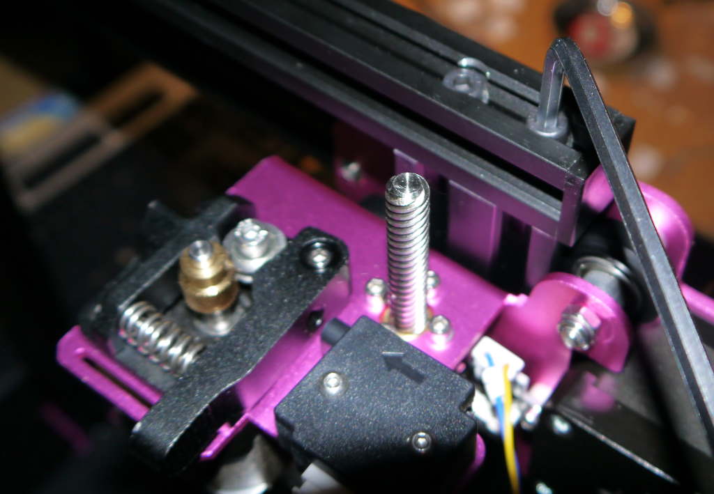 By tensioning the top last, everything is exactly positioned without any binding happening.
Now we have a nice square gantry, we can tighten the screws that hold the gantry to the frame.
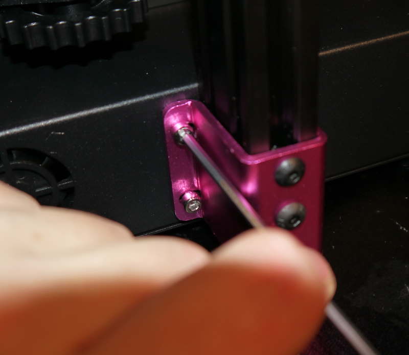 Tighten the screws at the bottom, then the screws at the top. Don’t apply too much force though.
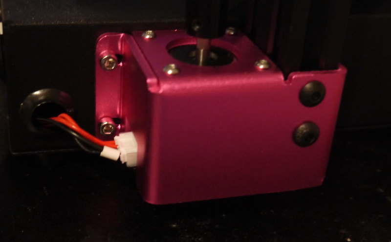 After you’ve tensioned the screws, don’t forget to plug in the Z-stepper motor.
X-axis - pulley assembly
The gantry is ready, let’s get the X-axis pulley ready. The hot-end will ride on the pulley along the X-axis. The pulley is driven by a belt, which is driven by a stepper motor. Before doing anything, you can put it on the X-axis first and once again tension the wheels using the eccentric nut.
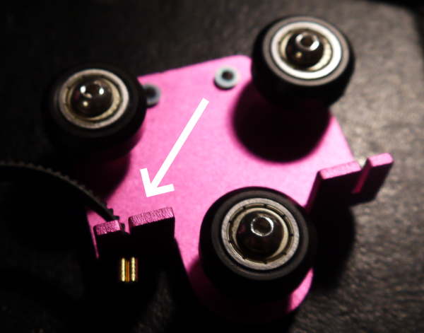 The belt has a metal crimp on each end. This metal crimp goes into the slot - aiming to the bottom.
The belt goes over the stepper motor gear, then in the aluminium extrusion back to the pulley. When you have one side of the belt attached to the pulley, you can put the pully on the X-axis.
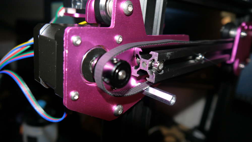 Note that the X-stepper motor has teeth which grab into the teeth of the belt
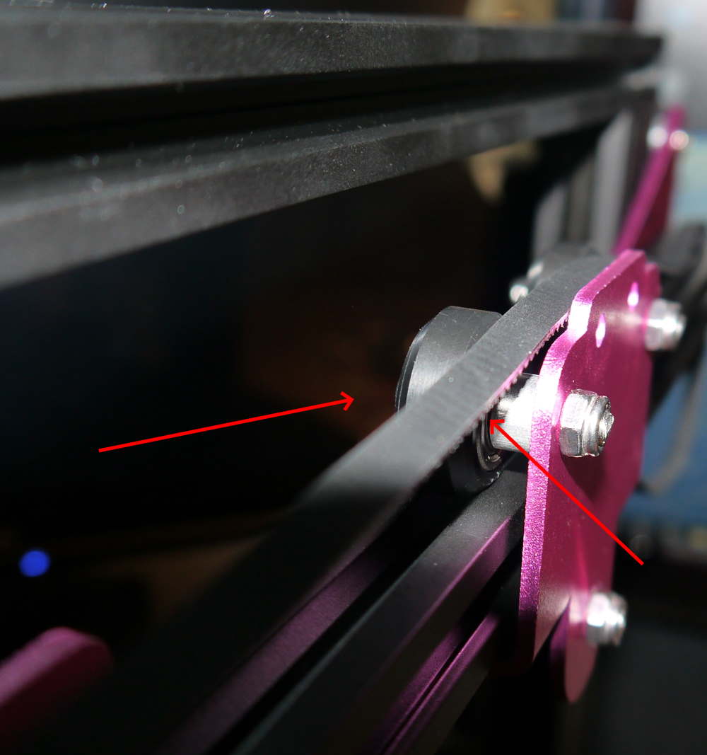 Wrong - In this case you have put the pully on the X-axis first before the belt. The belt must be situated below the wheels.
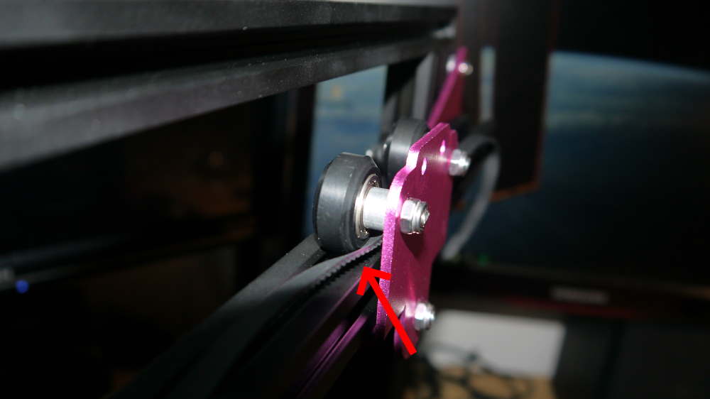 Wrong - The belt goes under the wheels - not parallel to them.
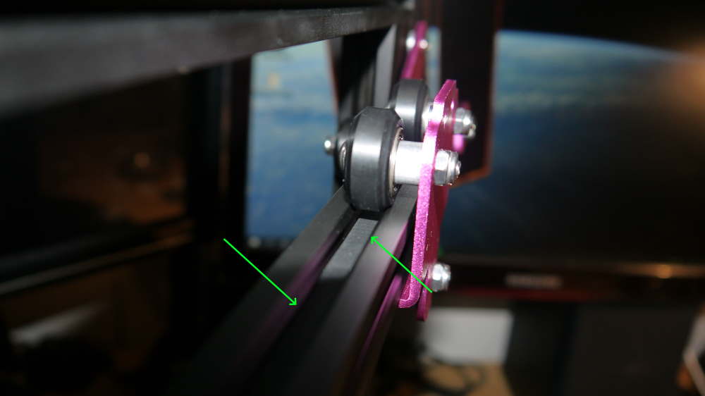 Correct - The belt is situated below the wheels.
X-axis - belt tensioning
The belt of the X-axis must be tensioned correctly, otherwise the printer will not be accurrate. For this you need to mount the belt tensioner, which also contains the idler on which the belt runs.
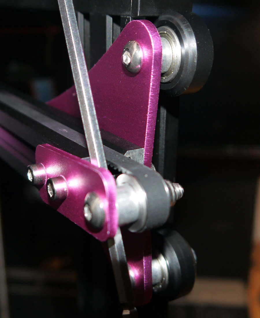 The trick I use for creating enough force is to take the Allen key and use that as leverage. Then you can first tension the innermost bolt, then the outermost bolt.
The belt is properly tensioned when it has almost no movement when you press on it. Don’t overtension it though, because it will wear out early or even snap.
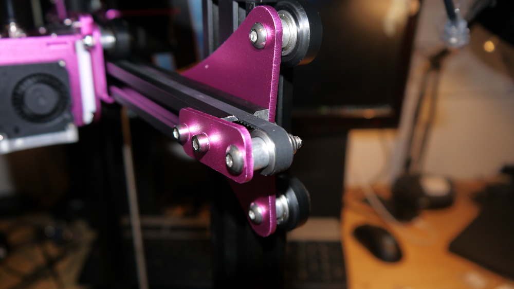 Properly tensioned. Do verify that the idler, aluminium extrusions are in the same straight path and don’t allow the belt to rub.
Hot-end and spool holder
The hot-end is already pre-assembled. Mounting this is as easy as mounting the two bolts.
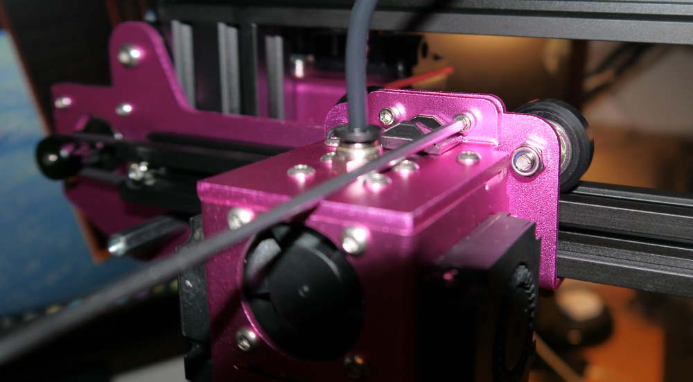 Ensure not to drop the hot-end while assembling. It might be the most delicate equipment on this printer.
The spool holder goes on the top of the printer - it has T-nuts that grab onto the aluminium extrusion.
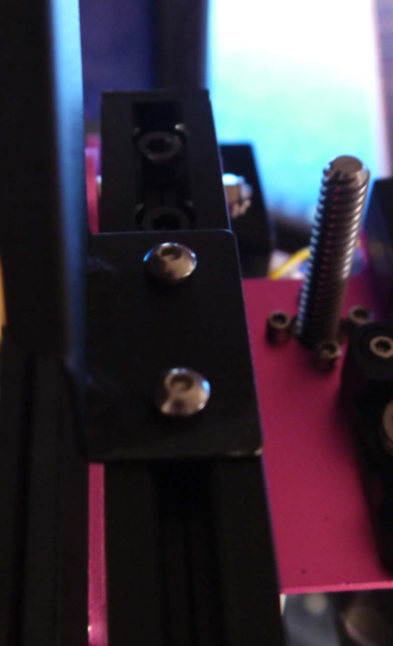 Note that the spool holder goes near the Z lead screw and essentially has a overhang.
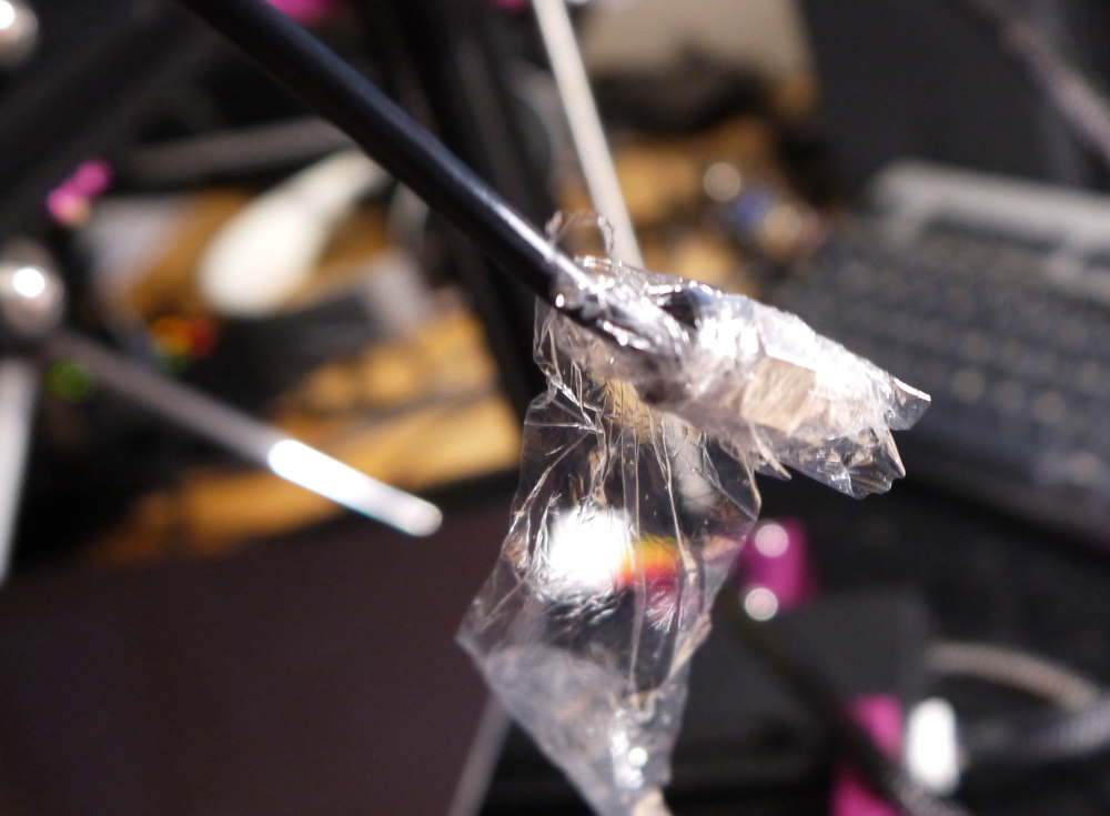 The path for the filament, the bowden tube, is wrapped in plastic. Unwrap it.
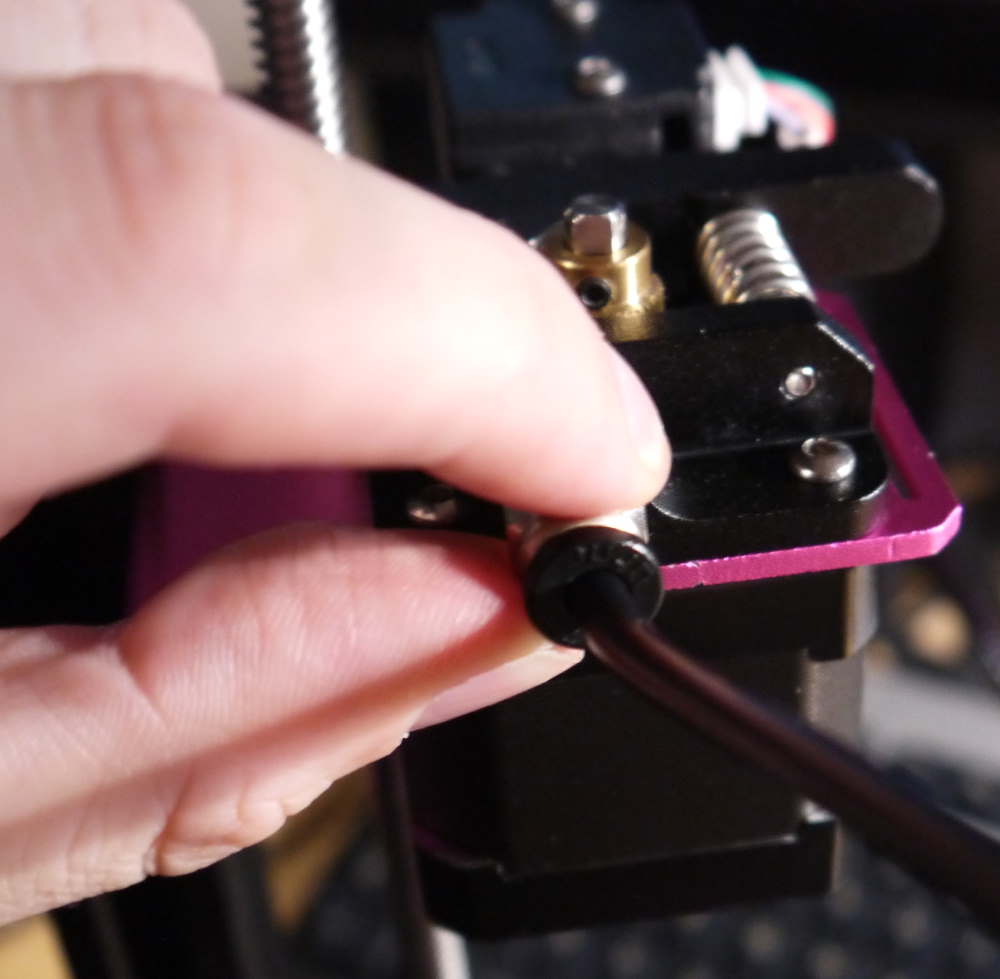 The bowden coupler screws into the feeder. Just hand tighten it. It will experience almost no rotational forces, so it won’t need to be screwed in with a wrench.
The hot-end gets its power from a USB-C cable. A very clean solution to what would be a mess of cables otherwise.
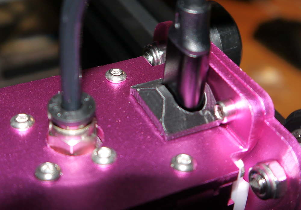 There is only one place it can go. Support the hot-end while plugging in the USB-C cable.
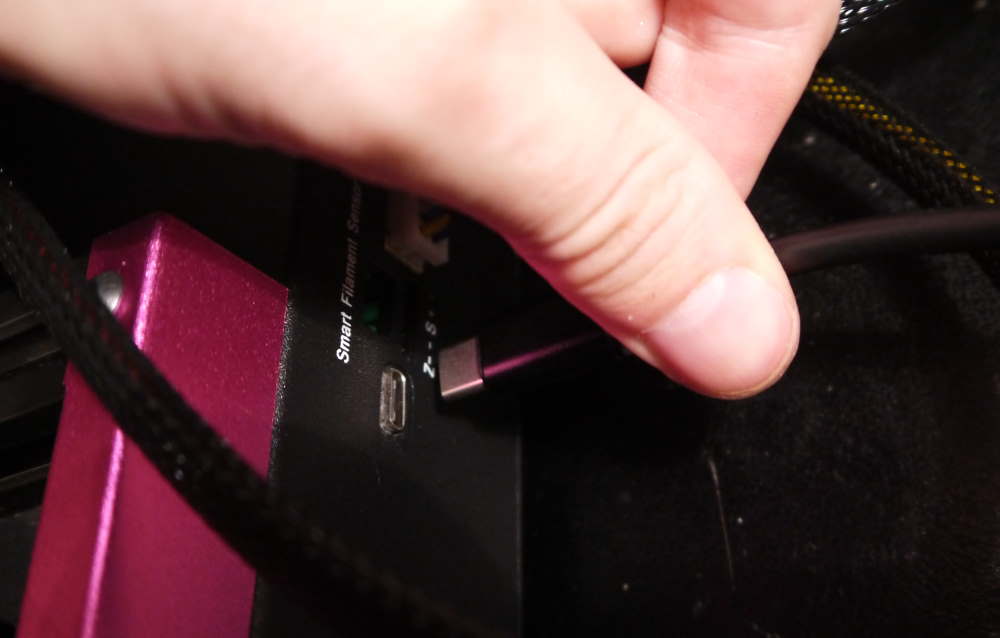 The USB-C cable goes to the back-side of the printer.
End-stop
Install the Z-axis endstop. It goes in the small hole on the gantry.
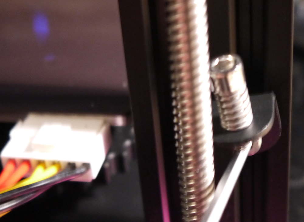 The Z-axis endstop is a spring with a bolt. This allows changing it if necessary (for instance, if you change to a higher buildplate)
This is a good opportunity to calibrated the Z-endstop. The combination of the bed leveling, the Z-endstop, and the height of the nozzle has the result of the nozzle hitting and scratching the bed, not hitting the bed at all, or having a nice even first layer.
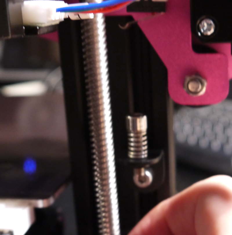 Turn the Z-axis coupler to slowly decrease the position of the X-axis until either the switch hits the endstop or the pink metal hits the endstop holder.
If the switch on the X-axis hits the endstop first, it is fine. Otherwise you will need to either unscrew the endstop bolt a bit so the switch is hit first. Ensure the nozzle does not hit the bed - or tension the bed screws as necessary.
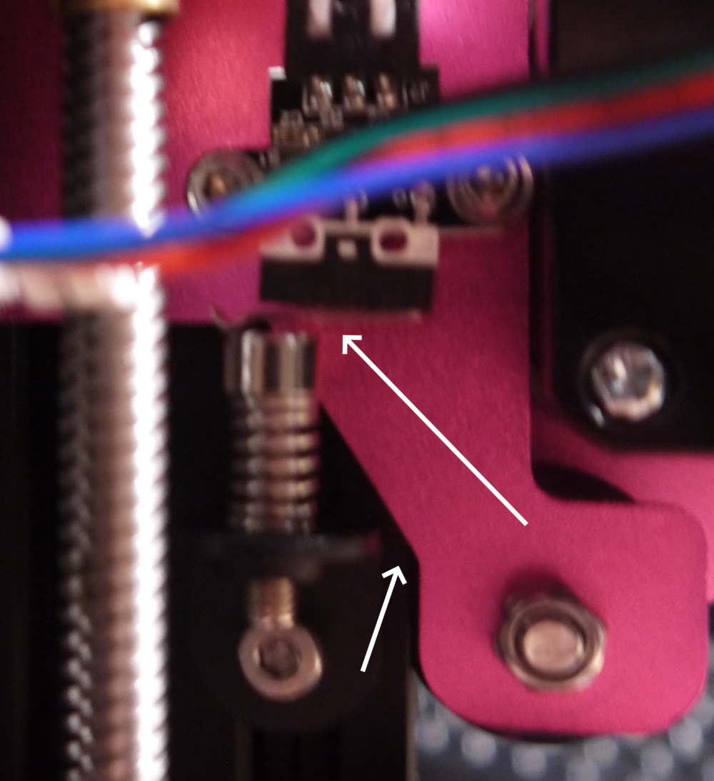 The switch clicks when it hits the endstop.
Cabling
There is some cable management to perform. First plug in the cables, then tidy them.
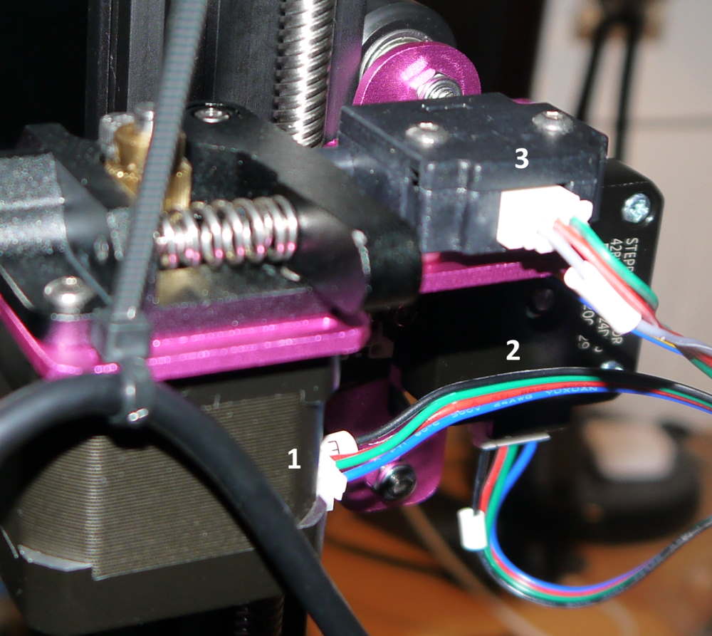 Plug in the extruder stepper motor (1), the X-axis stepper motor (2) and the filament runout sensor (3). The cables are labeled.
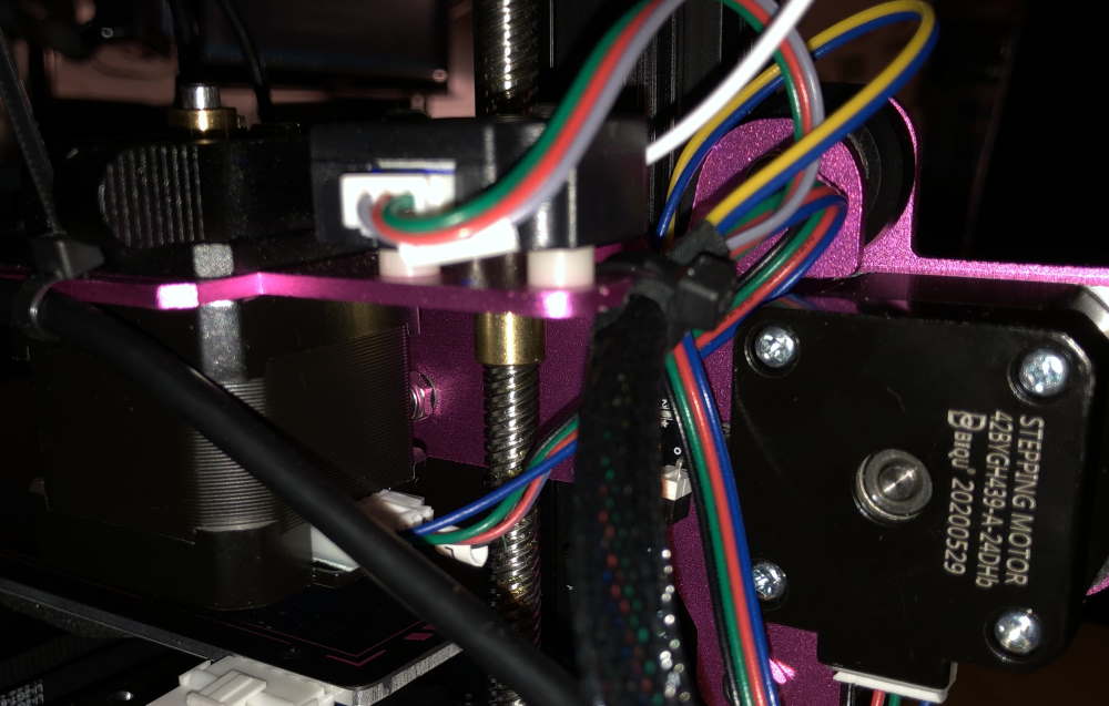 Use the included cable wraps to tie the USB-C cable to the bowden tube (2x), the USB-cable to the slot at the extruder, and the X-axis cabling to the pink metal.
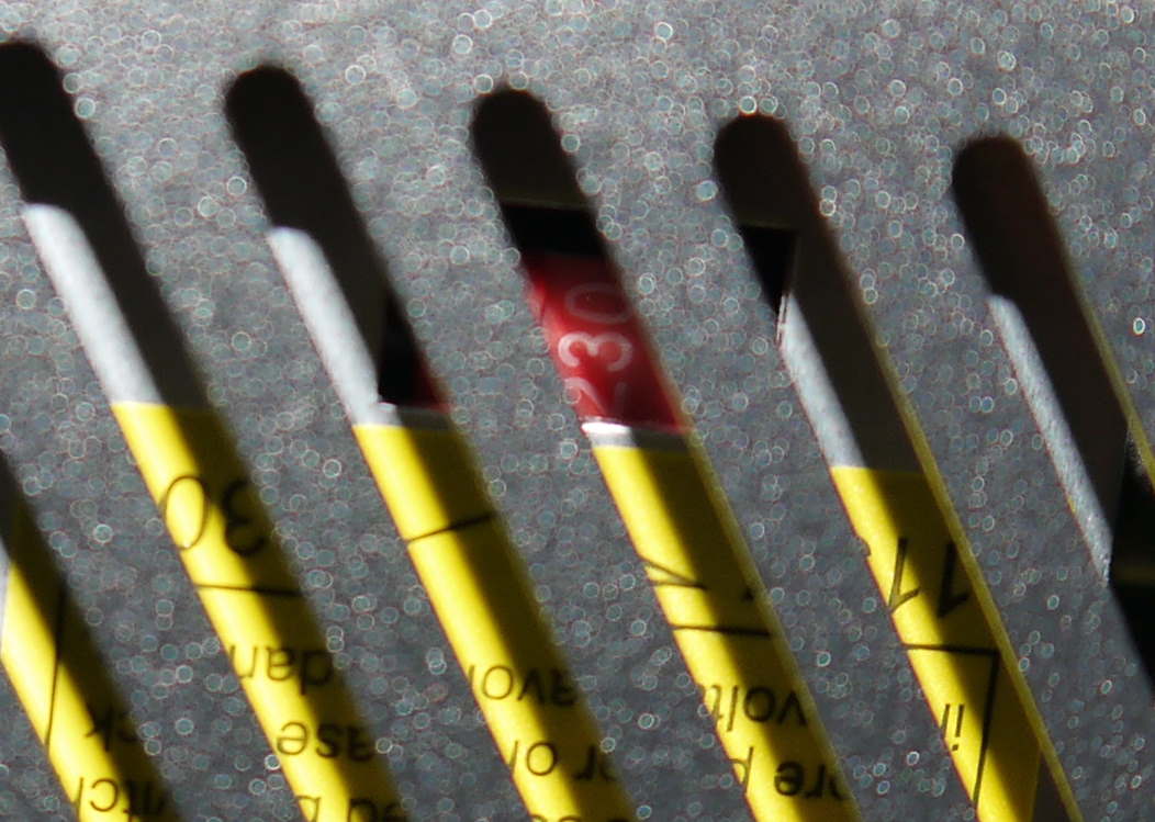 **Don’t forget to set the correct voltage for your country on the power supply.*
First boot
Now is the moment on truth… did you do everything right? Plug in the C13 connector at the rear side of the printer and turn it on.
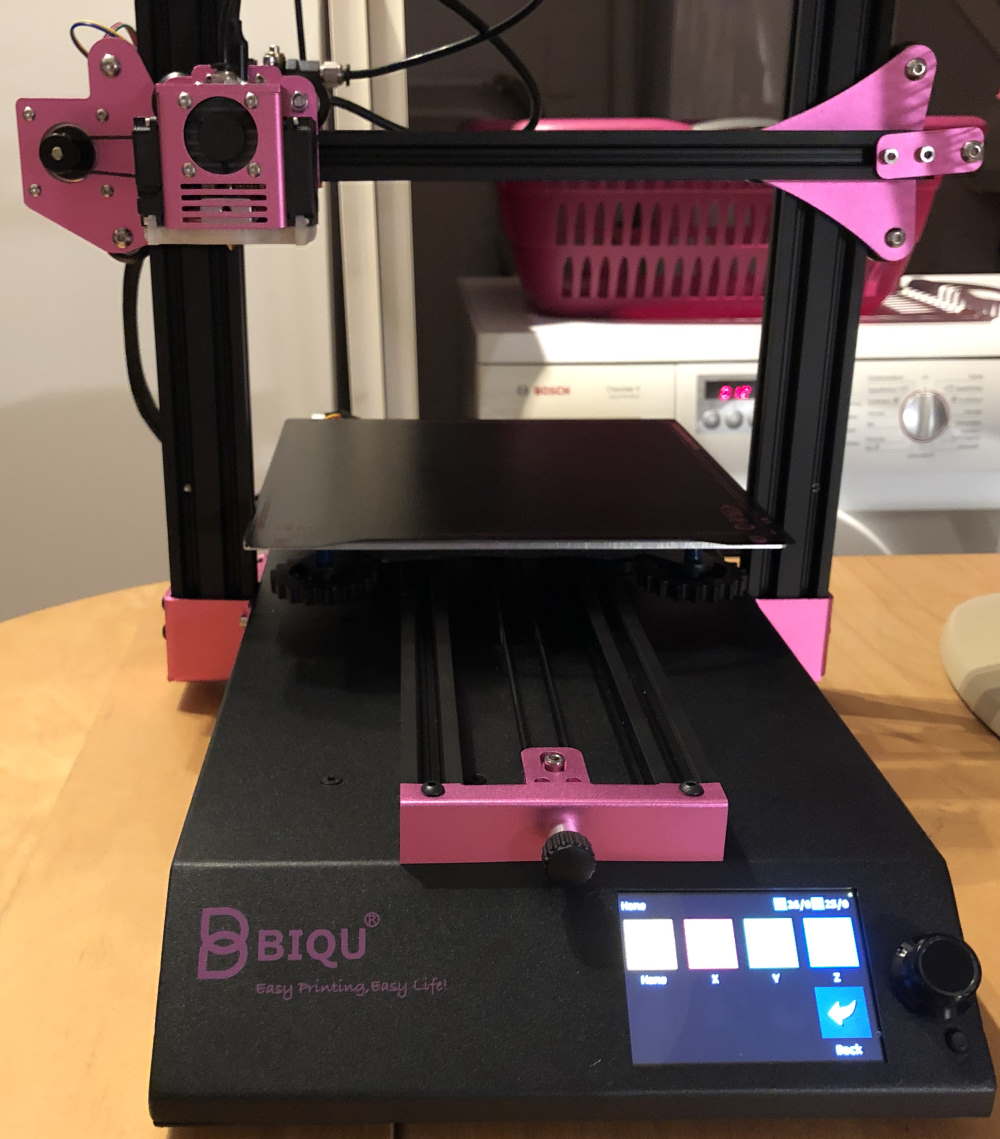 It’s alive! At the point I took this photo I already went to the movement screen to test the stepper motors.
Before you do anything, go to the “Motion” menu and home all axis. This command will move all axis to their respective end-stop sensors. At the point the position of each of the steppers is known to the printer.
After that, the next steps, which I will not cover today, are:
- Leveling the bed
- Doing a first test print
Until the next - where I will review the BIQU B1!
What are your thoughts?